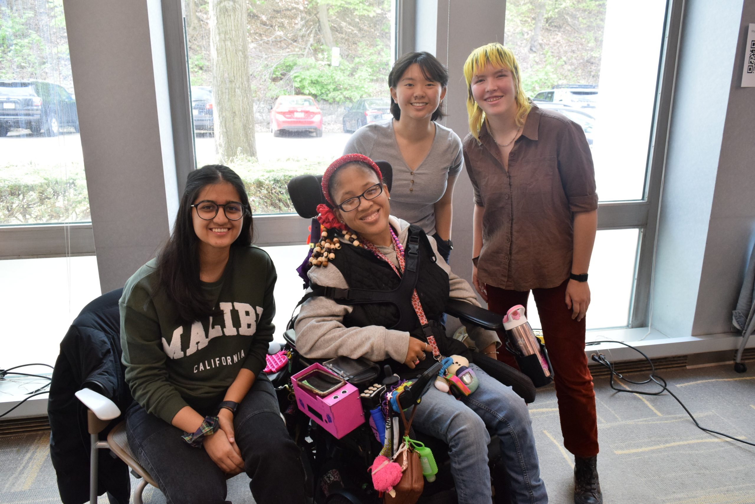
For this project, we were tasked to create an assistive device for a client with a disability. Our class focuses on small electronics and interaction, so we had to find a way to use those skills to create a device that would helpful for our client. We were connected to our client through CLASS, a local organization that provides a myriad of services for folks with disabilities. Over the course of six weeks, we met with our client, designed prototypes, tested prototypes, and finally created the final product. You can read more about the initial interview here.
What we built
We met with our client Darnisha and she told us how she would often set her phone down and forget where she had placed it. Additionally, due to her mobility, she had trouble reaching over to turn off her alarm on her phone in the mornings. The solution that we came up with solves both these problems with one device. The device hooks onto her wheelchair armrest and has a phone holder that lights up when the phone is not there to remind her to locate her phone. The device can unhook from the chair and sit on her bedside table to act as an alarm clock that is turned off by waving her hand over a sensor.
The final phone holder and alarm.
This video demonstrates the alarm function. The alarm is preset to Darnisha’s schedule, as it is very consistent and does not change often. When the alarm goes off, Darnisha turns it off by simply waving her hand over the top of the device.
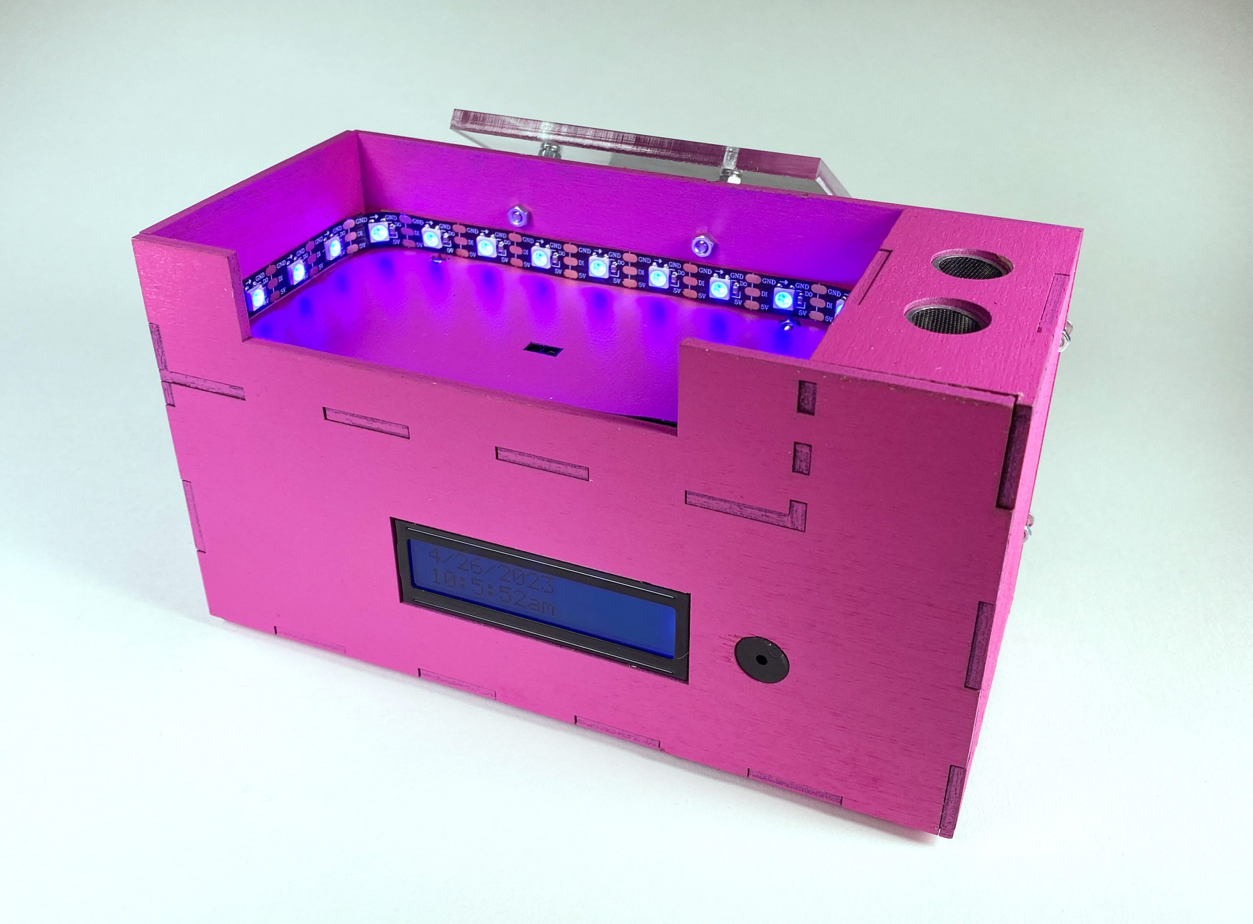
Here, you can see the phone holder function. There are flashing rainbow lights that display when the phone is not in the slot to remind Darnisha that her phone is not on her. With the help of an IR sensor, when the phone is placed in the slot, the lights turn off.
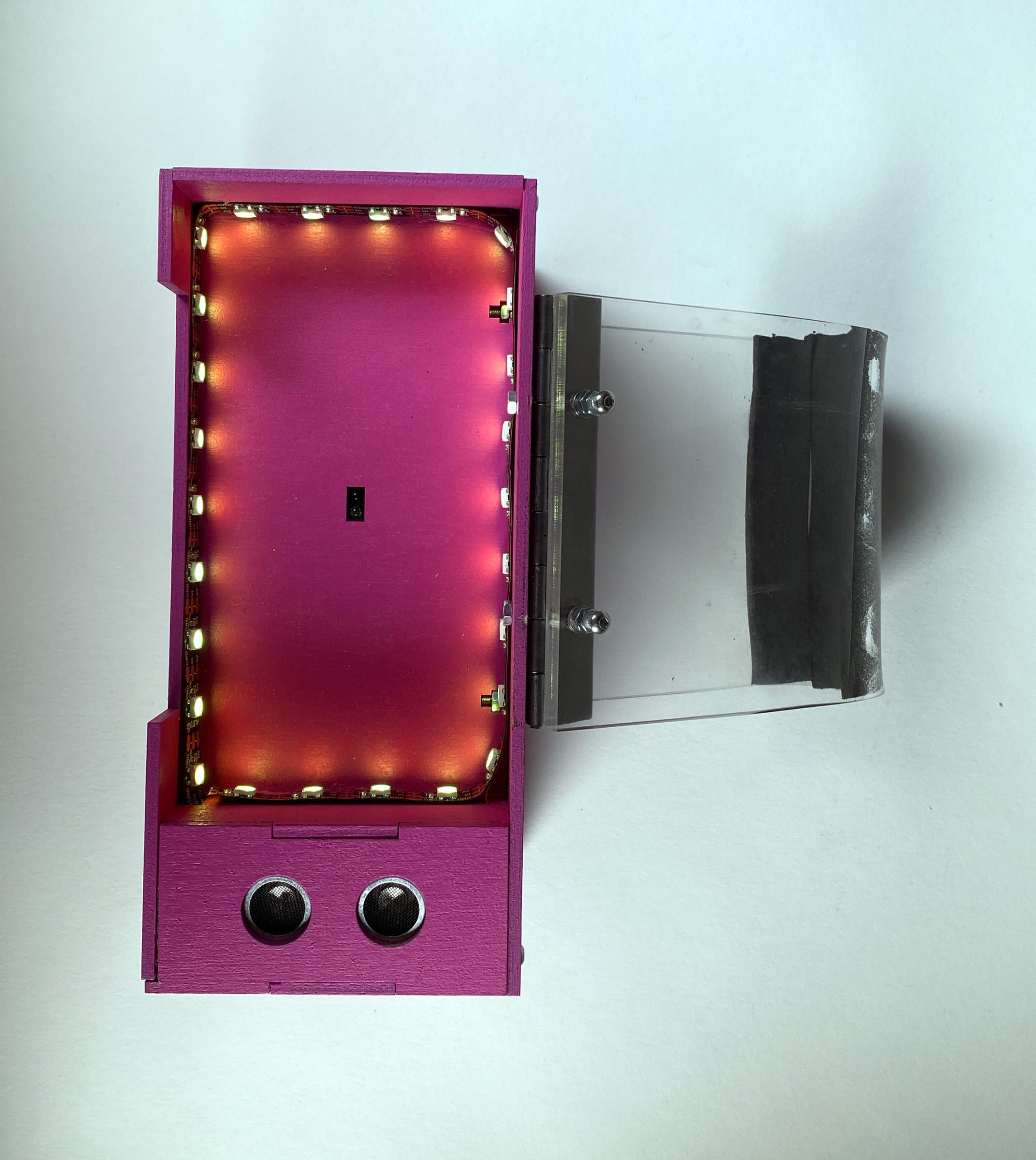
The top view of the device. Here, you can see the small IR sensor in the middle of the phone slot, and the ultrasonic ranger on the side which turns the alarm off. Also shown here is the handle, which was laser cut acrylic that we then bent with a heat gun to fit the curve of Darnisha’s wheelchair armrest.
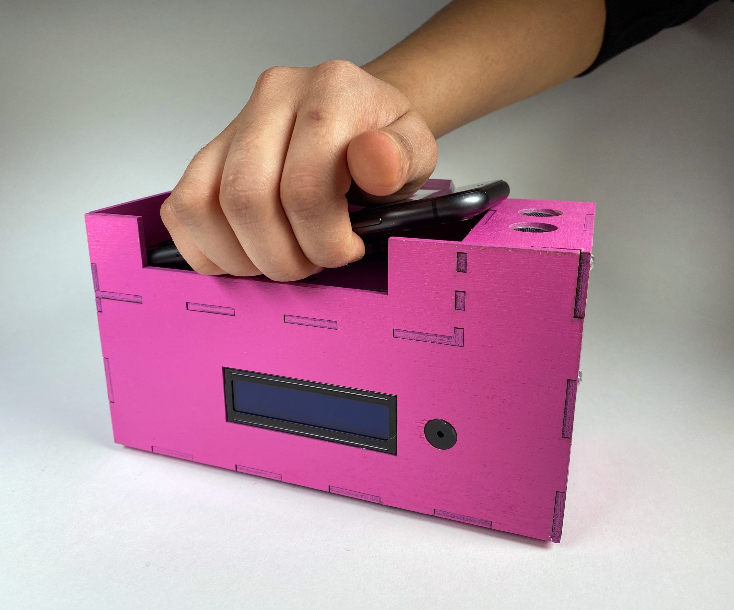
Darnisha’s phone lays diagonally in the slot to allow for her to easily grab the phone from underneath.
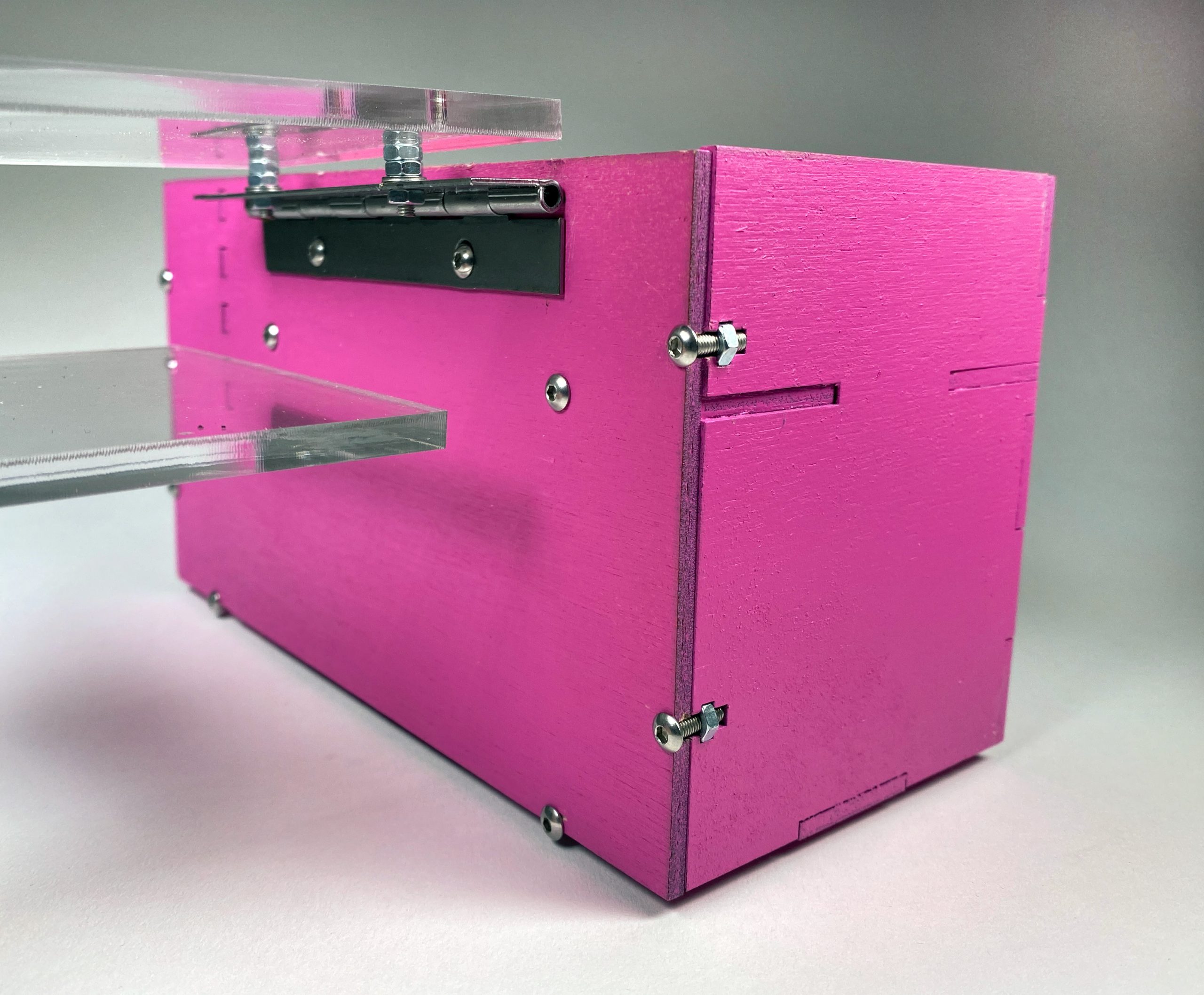
We made the back panel of the device removable in order to access the electronics inside. We achieved this by using small “T” joints with a bolt and nut. Additionally, we used a piano hinge so that the handle can lift up, slide over the armrest, and the device hangs over the side.
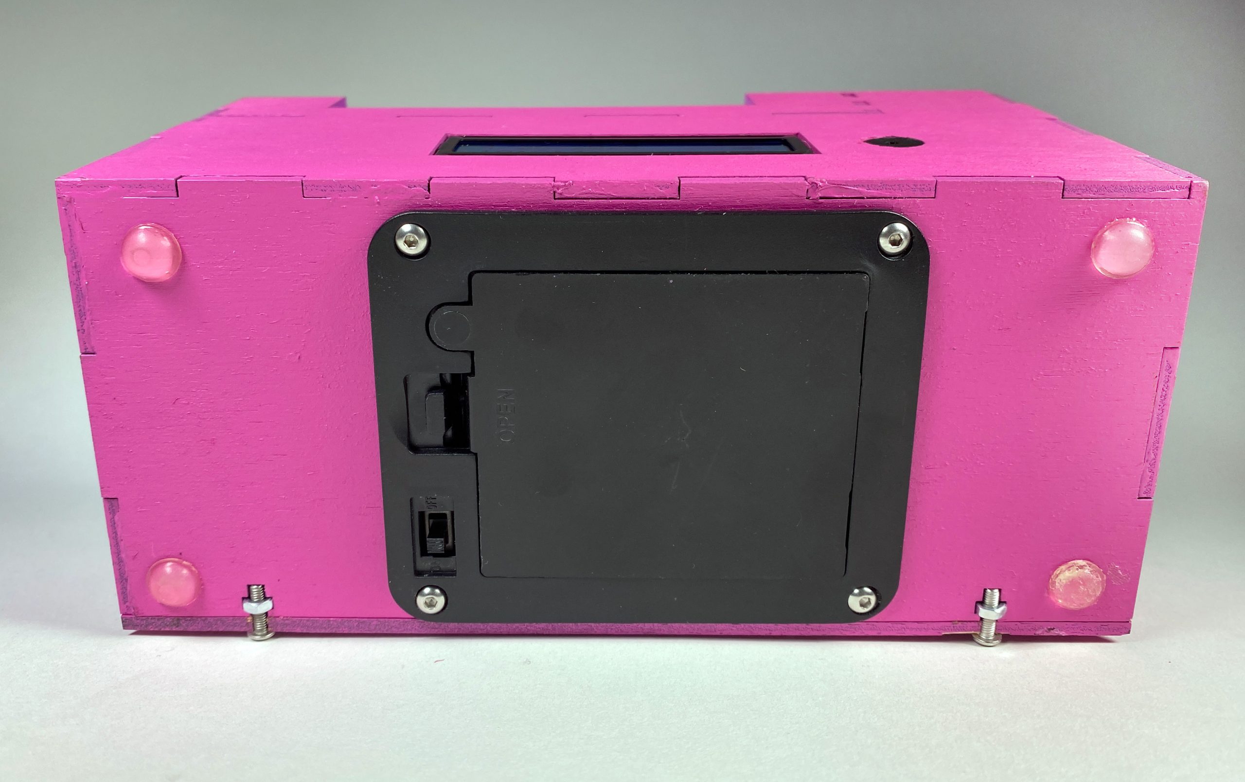
Show here is the bottom of the device, where there is a panel mount battery pack to easily change batteries. This is also where the ON/OFF switch is located.
A narrative sketch –
When Darnisha gets up in the morning she reaches out to her side table where her phone holder and alarm sits. As the alarm goes off the display screen says Get Up!!! She waves on top of the ultrasonic sensor to turn off the alarm.
After she is all ready for her day, she attaches her phone holder to her wheelchair which helps her keep her phone at a more accessible position and avoids her from misplacing her phone. As Darnisha picks up the phone to use the LED strip lights up indicating her that the phone is missing from its position.
How we got here
Prototype
The fabrication prototype was designed to determine the best way for the device to attach to Darnisha’s wheelchair. The electrical prototype was designed to determine a couple questions: would the alarm be loud enough for Darnisha? Did Darnisha want to set her alarm each day or have it preset in the device? What color and brightness would be best for Darnisha?
The first prototype was designed to sit on top of the armrest, and have the ability to swing out over Darnisha’s lap to act as a phone stand while she uses her phone. Additionally, we had an electrical prototype of both the LED function and the alarm function. The LEDs are connected to an IR proximity sensor. When the sensor is covered, the lights are off, and when it is not covered, the lights turn on. The alarm was shown on an LCD screen. The alarm time was inputted by and numerical keypad. The alarm is turned off by waving over an ultrasonic ranger.
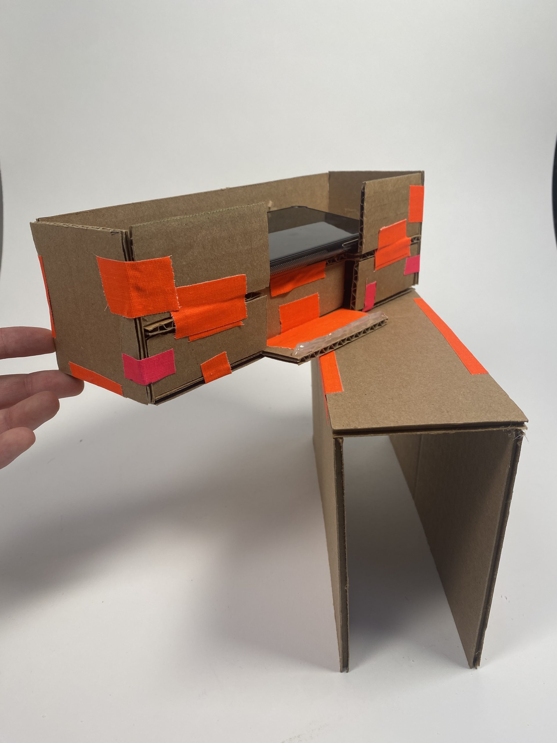
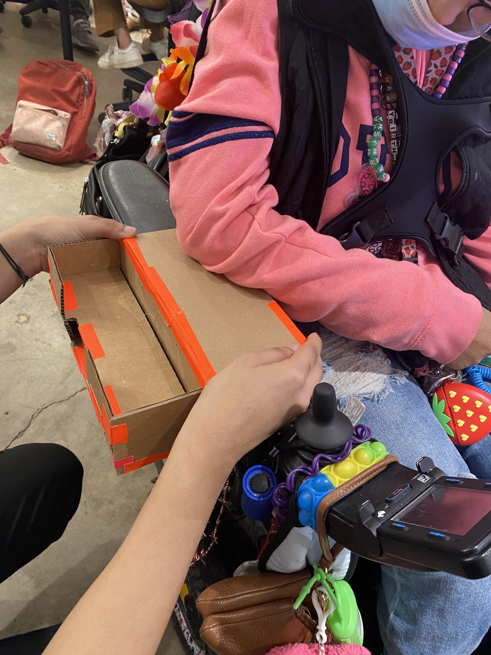
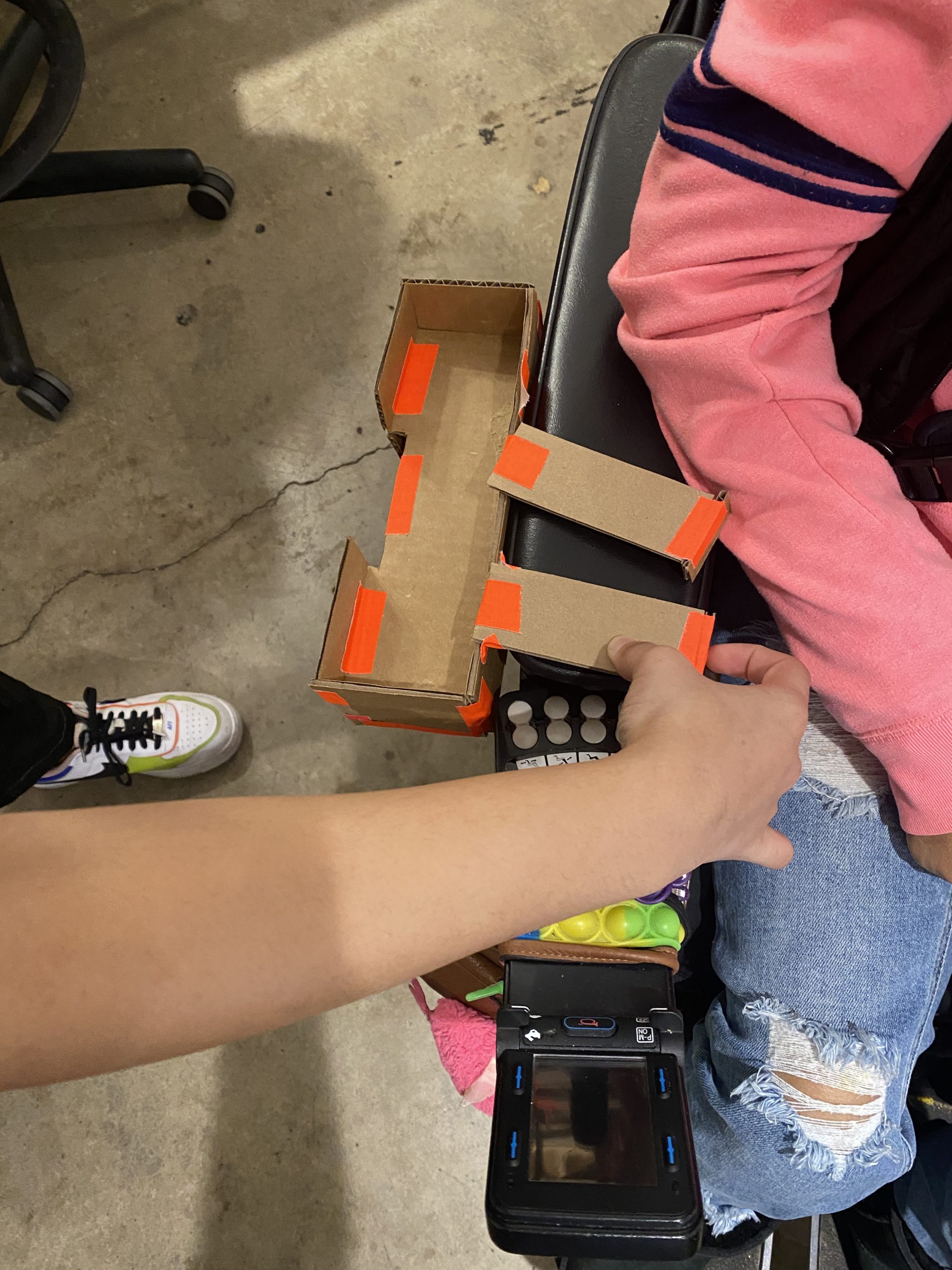
The cardboard prototype of the physical device.
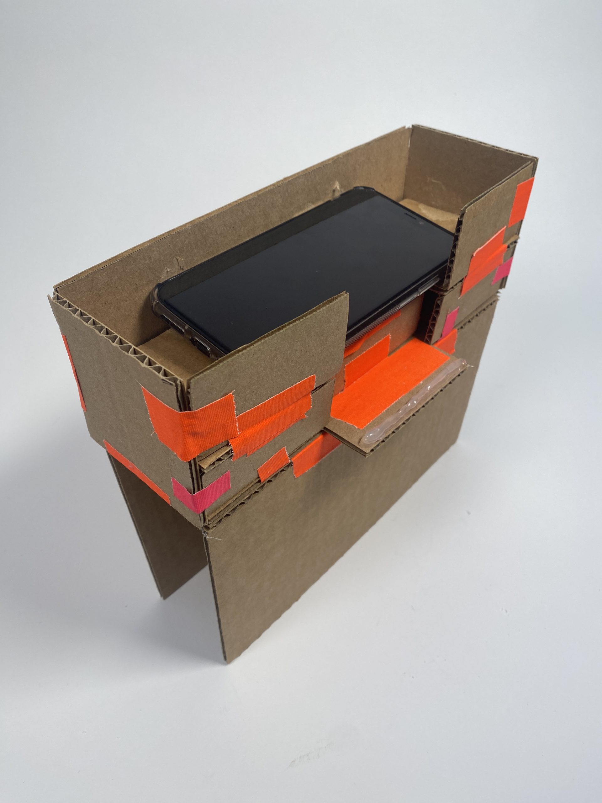
This prototype was meant to sit on top of Darnisha’s armrest.
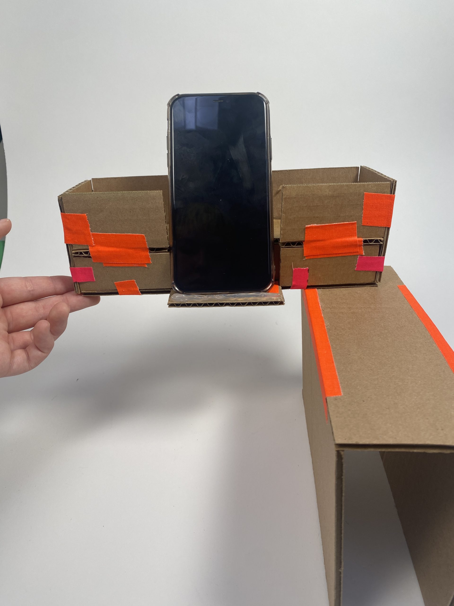
The top of the device swivels out to provide a phone prop for Darnisha to use while on her phone.
The prototype for the LED lights that turn on and off based on the IR sensor input.
The prototype for the alarm turned off by an ultrasonic ranger.
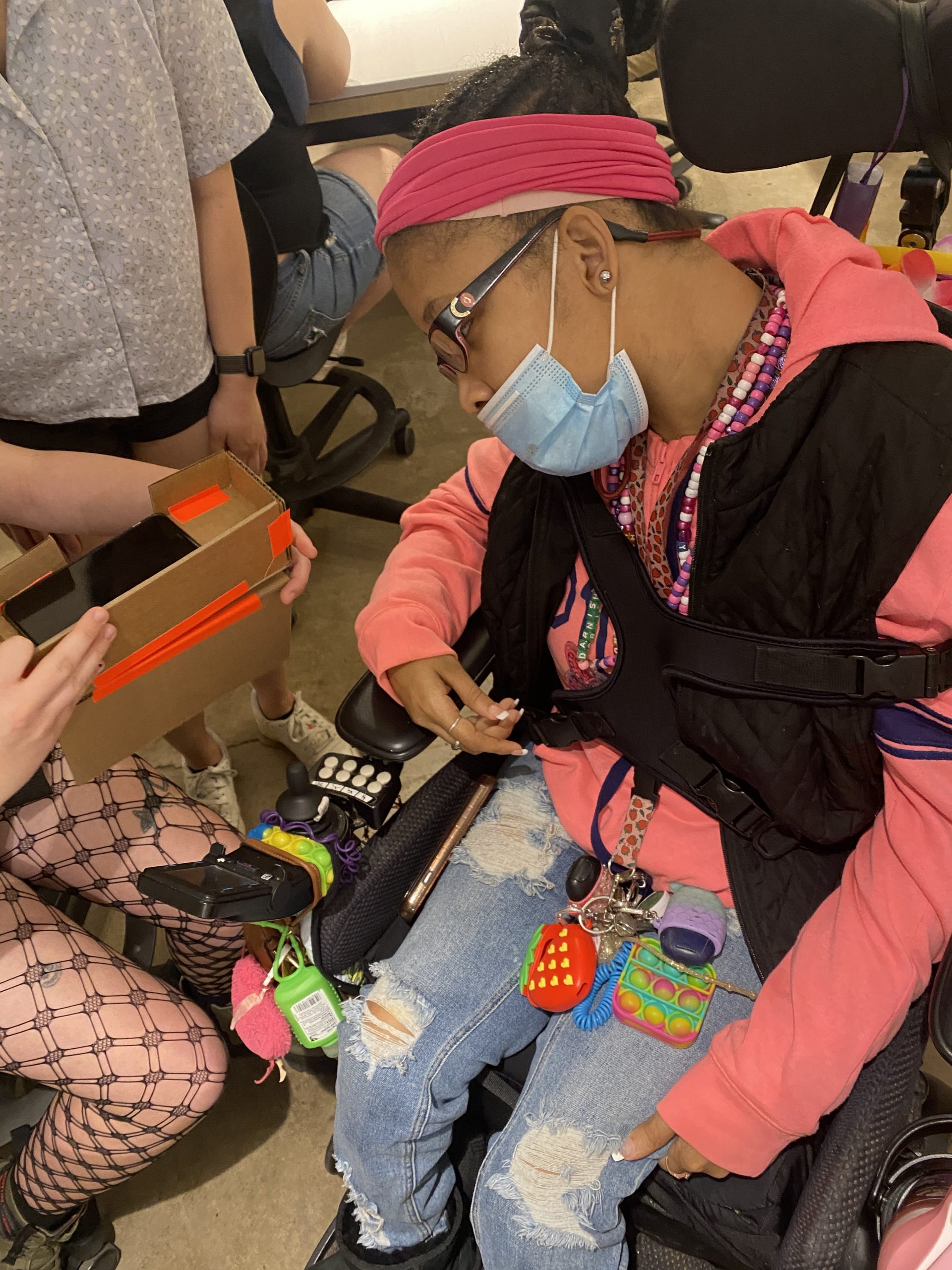
Showing Darnisha our first prototype design.
Here, we realized that having the device on top of her armrest would inhibit her use of the armrest. She decided that the swivel part wasn’t necessary for her and it would be more useful on the side of her chair.
We also tried out some alternative handle designs.
Throughout the prototyping process, we tested a variety of ways for the device to attach to the wheelchair, including it sitting on top of the armrest, connecting to a bar below the armrest, and hooking over the armrest, which is what we ended up going with. This choice still allowed for comfortable use of the armrest, and the device was still close enough that Darnisha could easily grab her phone. We also used this time to get as many measurements of the armrest as possible so that we could make the fit perfect, as this would be the last time we would see Darnisha in person before the final critique.
As far as the electronics, Darnisha decided that the buzzer we had used would be loud enough and wouldn’t need volume control. We learned that her schedule is very rigid and doesn’t change often, so she wanted the alarm times to be preset in the device. This meant that we would get rid of the keypad. Finally, we asked about the light brightness and color. Darnisha liked the brightness of the lights, and asked for them to be rainbow and flashing.
Process
Once we received feedback on the prototypes, we got into the process of creating the final device.
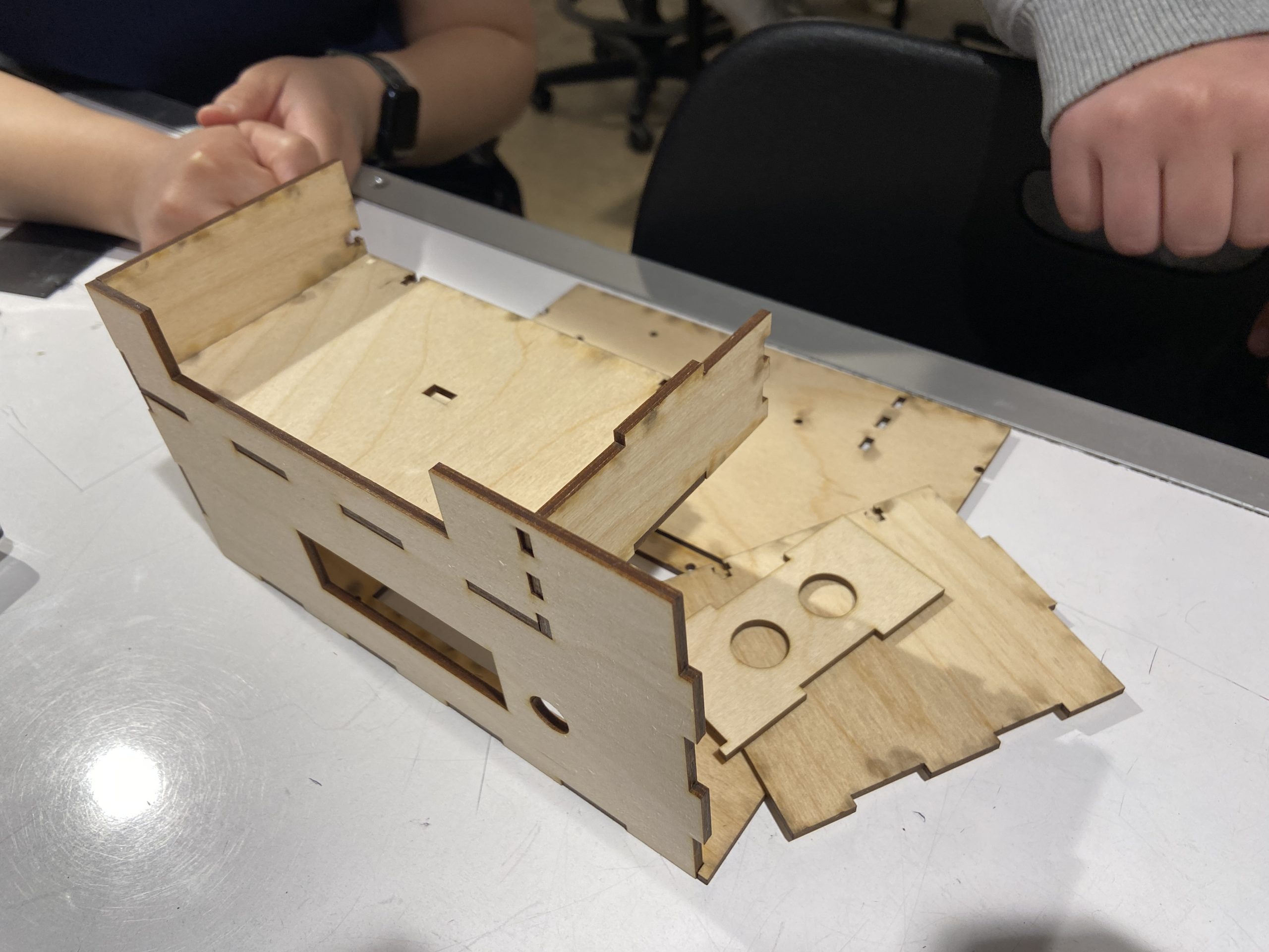
Assembling the laser cut pieces. Somehow, all the pieces and components fit together on the first try, which was really exciting.
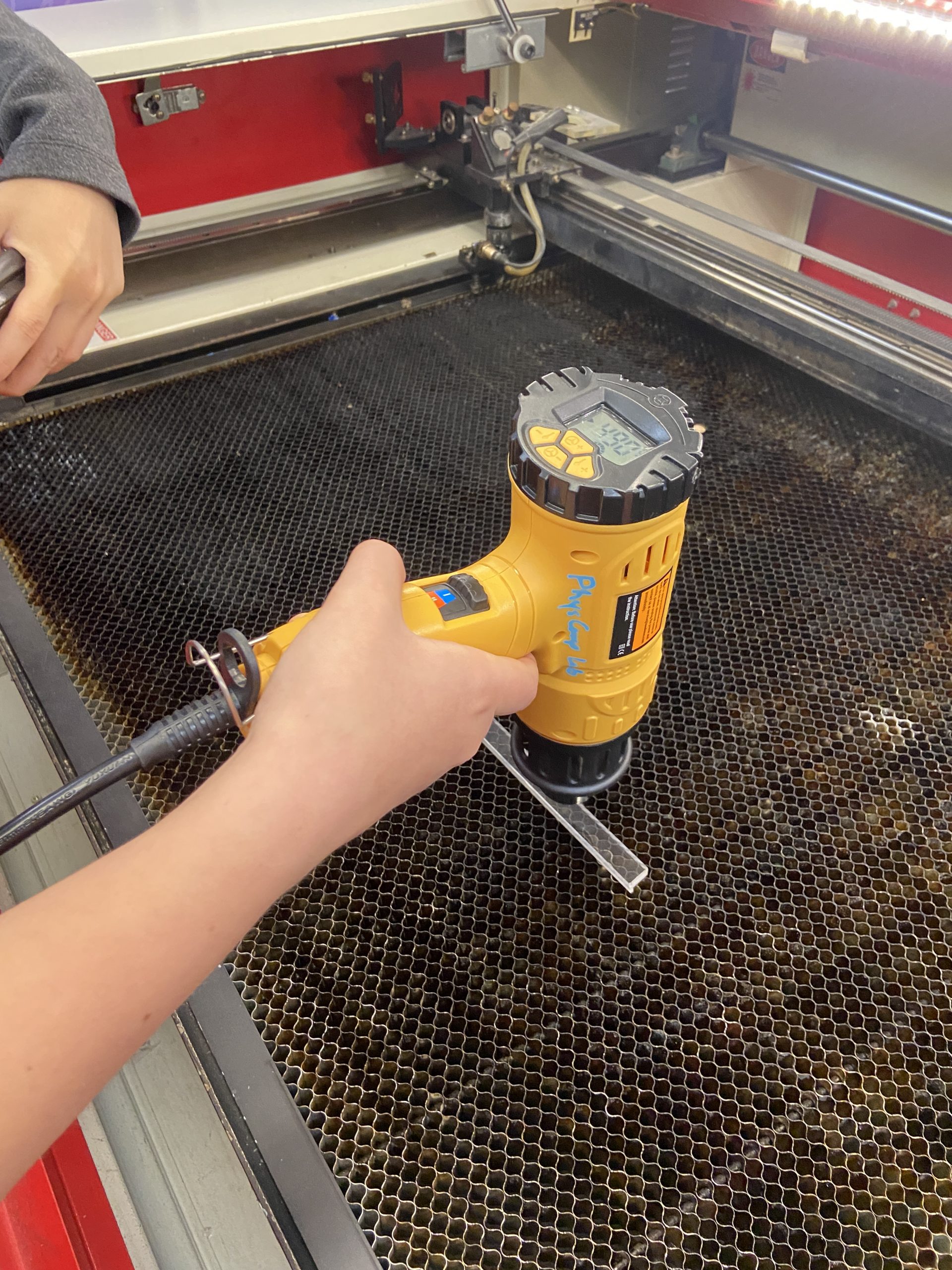
Here we tested out bending acrylic with a heat gun on a scrap piece.
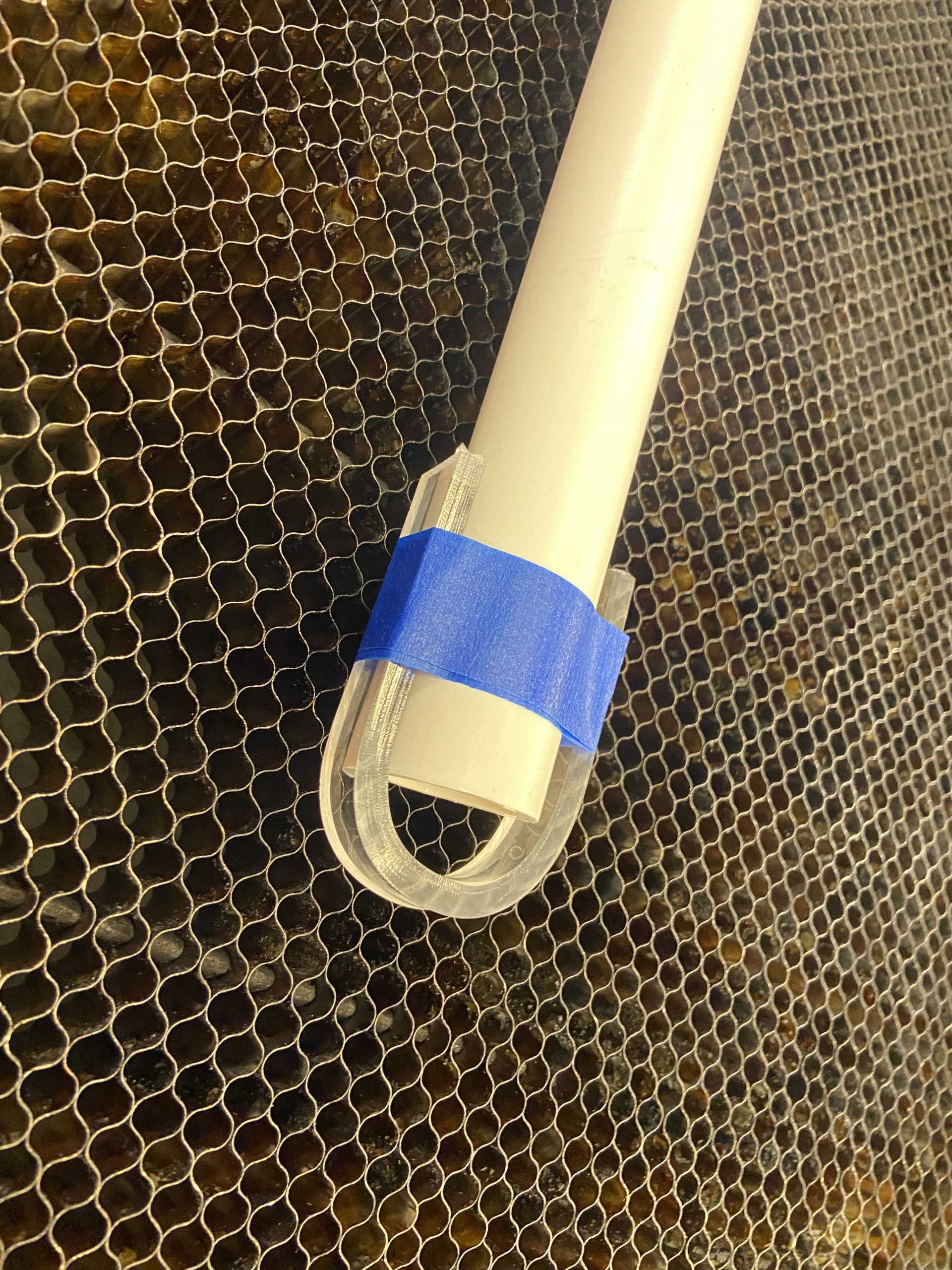
Once we heated the acrylic till it was pliable, we bent around a PVC pipe that roughly matched the curve and diameter of the armrest.
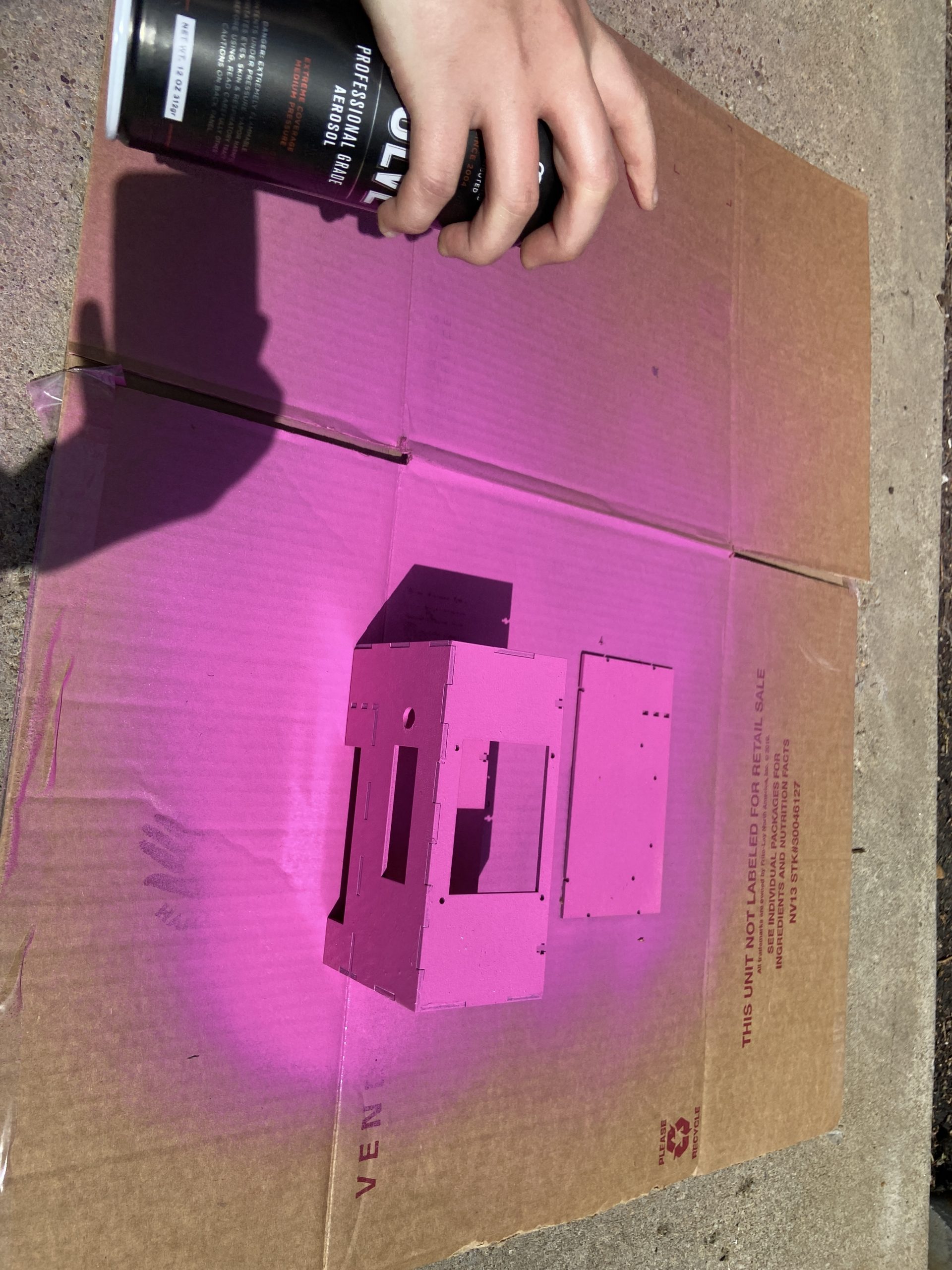
Once we had mostly assembled the box, we spray painted it Darnisha’s favorite color – pink!
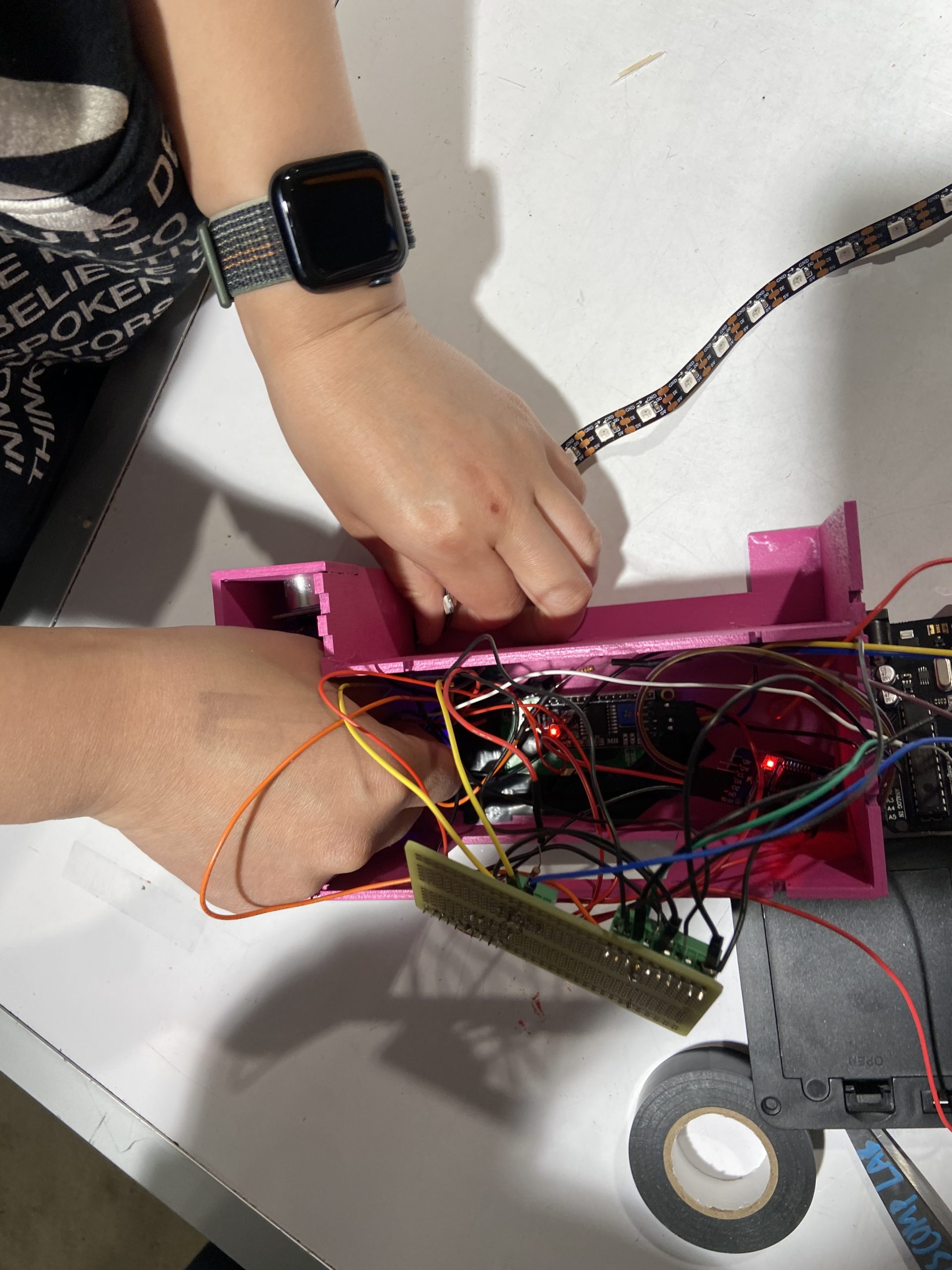
Then, we began assembling all the electronics inside. The holes and slots that were cut for the components were almost an exact fit, so it took some patience so get everything into the right spot.
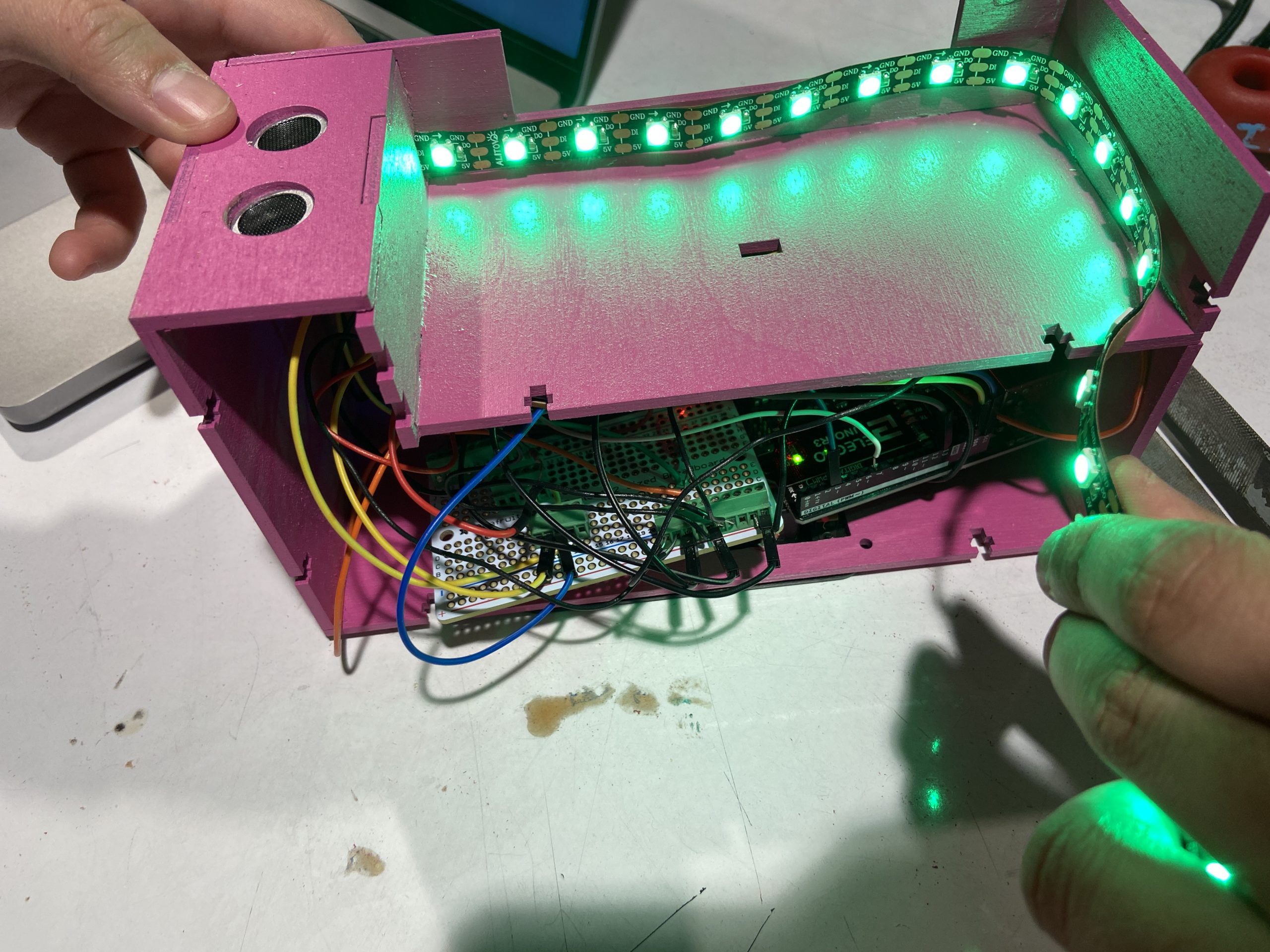
Here, you can see everything in place, except for the back panel. The back panel is secured with t-joints with small nuts and bolts. It’s very secure, but can be removed if necessary to get to the electronics.
We got good feedback from Darnisha in terms of her preference for position, light, and usage during the prototype crit and her being in person helped us get the wheelchair measurements, which made it easier for us to design the attachment to the correct size. However after digitally prototyping the model and assembling it, we realized that there was an issue with the size of the phone holder. Even after measuring Darnisha’s phone size we should’ve added some allowance in the width and height, taking in consideration if she changes her phone that is bigger. Phone in the space was not laying flat because of the size issue but we framed it as a very happy accident by saying that ” Darnisha’s phone actually doesn’t lay flat, but that’s a feature and not a bug because it makes it easier to grab out of the device.” This was the major breakthrough during our process.
After analyzing the whole product we also realized that the LED strip was exposed and that it might not be the best decision in terms of safety for the product and the user. However we had fabricated and assembled the whole product, but we definitely noted this point down for future consideration.
The Gantt Chart was very helpful in aiding us to plan and divide our work. We didn’t diverge from it and managed to keep to our original goals as we gave enough space for each task and left a decent amount of room at the end to do some final touch ups. For the tasks we split 2 v 1 depending on the task. For example, Mo and I started modeling the device and making laser cutter files while Michelle opted to combine our already tested code in bits and pieces and solder the electronics. The effort was distributed fairly and we switched places wherever needed. Throughout the process we made sure to check in with each other and cover up for the other if needed so that there is no lag with the work.
Conclusions and lessons learned
Salient Findings from Final Critique
Our final critique was very formative and valuable to us, and we definitely learned a lot from it. Most of the feedback seemed to be in the vein that the device was very solid, and a few more tweaks or features could improve it.
Time display is rudimentary. Day of week could also be helpful.
We had a few people point out that the time display could be improved by adding additional information, such as the day of the week. There was also a similar comment about the digits in the display being formatted somewhat unconventionally, due to the lack of leading 0’s before each digit. This is definitely something that may seem like a small detail, but in practice could greatly improve user experience with a simple fix. In a future iteration, we would update the code to do so.
I think it would be helpful if the device showed its current charge since it’s battery-powered — or if it could be recharged.
Adding an indicator for current charge is something that had never crossed our minds while we were designing the product, but would definitely be extremely useful in practice. During critique, it was pointed out that this is especially important, because having a device unknowingly die out in the middle of the night may be problematic since it would prevent the alarm from going off in the mornings. Adding a battery percentage, or even a low-battery indicator would help Darnisha prepare in advance for this.
I appreciated the design and approachability of the product, the lights and motion sensor to turn off the alarm were well planned out while remaining fun and remaining true to the client’s personality. The strawberries were a cute touch

We were really happy to receive this feedback, because it was really important to us that this device would be something that would be fun for Darnisha to be a part of and that would be really useful to her in practice. We put a lot of time and effort in our design considerations, so it was great to see this re-affirmed.
I was mildly worried about the durability of the design and the security of the phone throughout perhaps a busier day.
We felt that this feedback was definitely a very relevant concern, especially after learning from Darnisha that there may be some difficulty keeping her phone in the holder when she boards the ACCESS transit service. In the future, we could use a more durable material or add additional reinforcements, other than just the wood glue.
Major Takeaways
- Often, devices and tools for disabled folks are often made by taking something else and tweaking it to fit their needs. It was very cool to be able to create a device fully for our client’s needs from the beginning. We could really take her abilities and desires into account and make it perfect for her, and not worry about making it “marketable” in any way.
- Collaboration is crucial: Designing something for a person with a disability is not a solo endeavor, and instead requires a lot of listening and collaboration to truly understand their needs. This project was not only made for Darnisha, but with Darnisha.
- Small details matter: When designing something for a person with a disability, small details can make a big difference. Something as simple as the placement of a sensor or simple measurements can have a significant impact on the user’s experience. It is important to pay attention to these details and make adjustments as needed. Something challenging in this process was building the device to the exact dimensions of Darnisha’s wheelchair and phone size. In the end, while the device fit and came together well, we could’ve taken even greater care to get the exact dimensions.
Concluding Thoughts
Overall, it was a super amazing experience to get to work on this project with Darnisha. It was really cool getting to build this device from beginning to end, all the way from designing the device to putting together a final product that she loved and was customized to her needs. We learned a lot about fabrication and the importance of considering all the small details of a design and a user’s needs. With such a complex project, we also learned to break down big tasks into smaller ones and to keep things modular, whether it be in the code or general planning. We also learned the importance of building extra time into our schedule and to account for last-minute issues that might come up.
If we were to do the project a second time around, we’d double-check measurements even more than we already did to ensure that everything fit perfectly. This would also involve checking fit more carefully before assembling the project, so that we could make adjustments as needed. We’d also make sure to take into consideration the space that would be taken up by joints & connections at the beginning of the process. If we had more time, we’d also pay closer attention to different usability elements, such as the LCD time display and add more features, such as adjusting the alarm, snooze button, etc.
Technical details
Block Diagram

Schematic

Code
/*
* Phone Holder and Alarm
* Team Peaches: Mo Cambron, Juhi Kedia, Michelle Liu
*
* Code for a wheelchair attachment that lights up an LED strip
* there's no phone blocking the proximity sensor and has
* a motion-activated alarm clock functionality.
*
* Pin Map:
  variable name | mode | pin | description
  -----------------------------------------------
  PING_PIN | input | 3 | reads & emits ultrasonic ranger data
  LED_PIN | output | 7 | LED strip
  PROXIMITY_PIN | input | A0 | reads IR sensor data
  BUZZER_PIN | output | 13 | makes buzzing noise
*
* Credits:
* RTC alarm clock code & reference: https://adafruit.github.io/RTClib/html/class_r_t_c___d_s3231.html
*
* Understanding how the RTC needs to be coded and how the information
* from the RTC can be displayed on the LCD:
* https://www.youtube.com/watch?v=aJcncPB0GHg
*
*/

#include <Wire.h>
#include <RTClib.h>
#include <LiquidCrystal_I2C.h>
#include <PololuLedStrip.h>

#define I2C_ADDR 0x27 //LCD i2c stuff
#define PING_PIN 3
#define LED_PIN 7
#define PROXIMITY_PIN A0
#define BUZZER_PIN 13;
#define MAX_DISTANCE 200
#define LED_COUNT 27
#define PROX_THRESH 850

PololuLedStrip<LED_PIN> ledStrip1;
LiquidCrystal_I2C lcd(I2C_ADDR, 16, 2);
RTC_DS3231 myRTC; //Wiring of the RTC (CLK,DAT,RST)
//If  you change the wiring change the pins here also

// Alarm clock hours
const int WEEKEND = 12;
const int WEEKDAY = 7;

// note: change for demo purposes; should be 0 in actual version
int alarmMin = 0;

int proxState0 = 0;

unsigned long rainbowDelay = 7;

rgb_color on[LED_COUNT];
rgb_color off[LED_COUNT];

const int ALARM_TIMES[7] = {WEEKEND, WEEKDAY, WEEKDAY, WEEKDAY, WEEKDAY, WEEKDAY, WEEKEND};
int RAINBOW[7][3] =
{
  {255, 0, 0}, // Red
  {255, 30, 0}, // Orange
  {255, 200, 0}, // Yellow
  {0, 255, 0}, // Green
  {0, 0, 255}, // Blue
  {75, 0, 220}, // Indigo
  {148, 0, 211} // Violet
};

int hue = 0;

void setup() {
  lcd.init();
  Serial.begin(9600);
  lcd.begin (16, 2); //Initialize the LCD
  lcd.backlight();

  pinMode(PING_PIN, OUTPUT);
  pinMode(PROXIMITY_PIN, INPUT);

  if (!myRTC.begin()) {
    Serial.println(" RTC Module not Present");
    while (1);
  }

  // Uncomment on initial RTC setup to set the initial time
  // comment back out and reupload after initial setup, in order
  // to prevent RTC from resetting every time

  //  if (myRTC.lostPower()) {
  //    Serial.println("RTC power failure, reset the time!");
  //    // automatically sets the RTC to the date & time on PC this sketch was compiled
  //    //    myRTC.adjust(DateTime(F(__DATE__), F(__TIME__)));
  //    // rtc.adjust(DateTime(2023, 2, 20, 3, 0, 0));
  //  } else {
  //    myRTC.adjust(DateTime(F(__DATE__), F(__TIME__)));
  //    //    rtc.adjust(DateTime(2023, 3, 2, 10, 0, 0));
  //  }

  //  myRTC.adjust(DateTime(2023, 4, 26, 10, 0, 0));

  int* curColor = RAINBOW[hue];
  for (int i = 0; i < LED_COUNT; i++) {
    // on is red
    on[i] = rgb_color(curColor[0], curColor[1], curColor[2]);
  }
  for (int i = 0; i < LED_COUNT; i++) {
    // off is clear/nothing
    off[i] = rgb_color(0, 0, 0);
  }

  DateTime now = myRTC.now();
  Serial.print(ALARM_TIMES[now.dayOfTheWeek()]);
  myRTC.setAlarm1(
    DateTime(now.year(), now.month(), now.day(), ALARM_TIMES[now.dayOfTheWeek()], alarmMin, 0), // Set alarm time to 7 am
    DS3231_A1_Date // Set alarm to trigger when date & time match
  );
}

// Helper function to get Ultrasonic Ranger distance
int getDist() {
  pinMode(PING_PIN, OUTPUT);

  // Create a wave by alternating a HIGH and LOW pulse
  digitalWrite(PING_PIN, LOW);
  delayMicroseconds(2);
  digitalWrite(PING_PIN, HIGH);
  delayMicroseconds(5);
  digitalWrite(PING_PIN, LOW);

  // The same pin is used to read the signal from the PING))):
  pinMode(PING_PIN, INPUT);
  return pulseIn(PING_PIN, HIGH);
}

// Convert military time to AM/PM
int militaryToRegular(int militaryHour) {
  if (militaryHour == 0) {
    return 12;
  } else if (militaryHour <= 12) {
    return militaryHour;
  } else {
    return militaryHour - 12;
  }
}

// Display date on LCD
void displayDate() {
  DateTime now = myRTC.now();
  DateTime tomorrow = now + TimeSpan(1, 0, 0, 0);
  lcd.setCursor(0, 0);
  lcd.print(now.month());
  lcd.print("/");
  lcd.print(now.day());
  lcd.print("/");
  lcd.print(now.year());
  lcd.setCursor(0, 1);
  lcd.print(militaryToRegular(now.hour()));
  lcd.print(":");
  lcd.print(now.minute());
  lcd.print(":");
  lcd.print(now.second());
  lcd.print(now.hour() < 12 ? "am" : "pm");
}

unsigned long tm = 0;


// Flash rainbow colors on LED strip
void rainbow()
{
  if (tm % rainbowDelay == 0) {
    int* curColor = RAINBOW[hue % 7];
    for (uint16_t i = 0; i < LED_COUNT; i++)
    {
      on[i] = rgb_color(curColor[0],  curColor[1],  curColor[2]);
    }
    hue++;
  }
  tm += 1;
}

void  loop() {
  delay(100);
  DateTime now = myRTC.now();
  DateTime tomorrow = now + TimeSpan(1, 0, 0, 0);
  long val = getDist();
  int readVal0 = analogRead(PROXIMITY_PIN);
  proxState0 = readVal0 > PROX_THRESH ? 1 : 0; // whether or not proximity sensor is covered
  rainbow();

  if (proxState0 == 1) {
    ledStrip1.write(on, LED_COUNT);
  } else {
    Serial.println("off");
    ledStrip1.write(off, LED_COUNT);
  }

  displayDate();

  if (myRTC.alarmFired(1)) {
    while (val > 500) {
      tone(BUZZER_PIN, 1000); //You can modify the tone or make your own  sound
      delay(100);
      tone(BUZZER_PIN, 2000);
      delay(100);
      lcd.clear();
      lcd.print("Get up !!!"); //Message to show when the alarm is ringing
      val = getDist();
    }
    lcd.clear();
    myRTC.clearAlarm(1);
    myRTC.disableAlarm(1);

    // set alarm for tomorrow
    myRTC.setAlarm1(
      DateTime(tomorrow.year(), tomorrow.month(), tomorrow.day(), ALARM_TIMES[tomorrow.dayOfTheWeek()], 0, 0),
      DS3231_A1_Date // Set alarm to trigger when date & time match
    );
    noTone(BUZZER_PIN);
    delay(100);
  }
}
Design Files
Here, you can access the design files used to model and laser cut the device: Design Files
]]>
Meeting agenda:
- Introduction/ice breaker
- Name, major, year, interests
- Talk about daily routine
- Ask about her daily routine
- Ask why she wants to participate in the project
- Explain our personal assistive device projects
- Explanation and clarification about project goals
- We are:
- Trying to build prototype useful devices
- Taking about seven weeks to go from this meeting to a reasonably high-fidelity final product
- Documenting our process
- We are not:
- Professional technologists who are experienced in making polished products
- Planning to build something that will be sold commercially
- Constrained by any practicality outside of usefulness to the person we’re designing for
- We are:
- Quickly go over timeline again
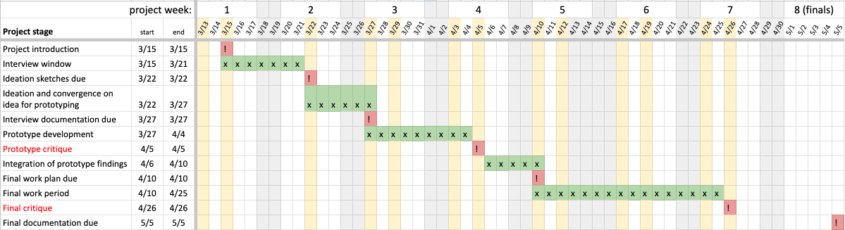
Project timeline.
- Understanding needs and thinking of possible technological interventions
- Interests
- Daily routine
- Ask directly about difficulties
- Follow-up asking for demonstration
- Ask if there is anything she used to enjoy that has now become difficult
- Experiment with quick prototypes
- Conclude
- Thank client for their time, make sure they have your contact information.
Meeting summary and major takeaways:
First, we did some brief introductions and went over the goals of the project again. We explained what we are trying to accomplish, and what we are not trying to accomplish with the project. During this part of the discussion, we also talked about the devices we each made for our personal assistive devices to give her an idea of the types of projects we could make for this course. Then, we went over the timeline of the whole project to make sure we are all on the same page.
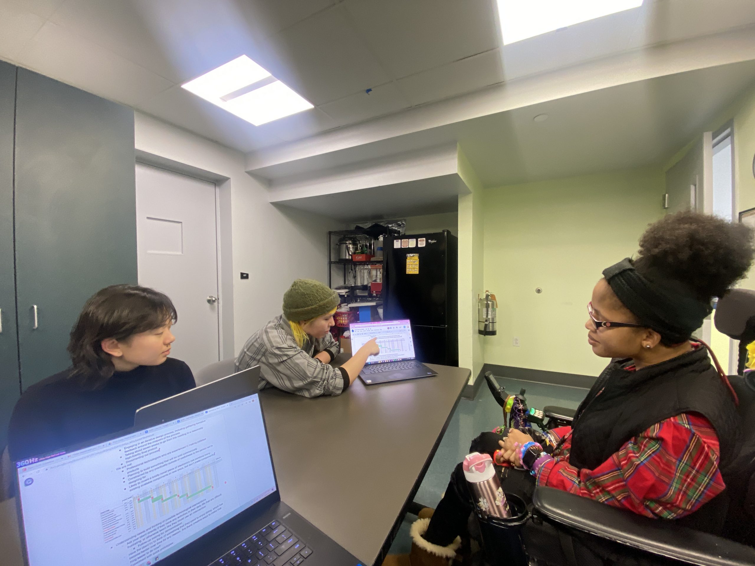
Going over the timeline with Darnisha.
We discovered a lot about Darnisha’s interests. She is a very creative person and likes to express that in many different ways. She enjoys painting, watercolor, collage, cut and paste, and other arts and crafts. She also loves fashion (She had just won “Best Dressed” at a camp over the weekend!). She particularly enjoys accessorizing with jewelry and beads. Her favorite colors are pink and purple. She really enjoys these activities, but her limited mobility can sometimes make it difficult for her to fully enjoy them.
We also discussed a bit of her daily routine. Some things she mentioned that she has difficulty with is putting on socks and shoes, because she is unable to bend over or pull them up. She also mentioned that she struggles to remember where she puts her phone down sometimes.
Once we had discussed some of her interests and daily routines, we talked a bit more about specific ideas. We talked about some difficulties with arts and crafts. She mentioned that she enjoys using various cut out shapes in her creations, but struggles with the action of cutting. She said that she typically uses a few set shapes in her crafts— circles, squares, rectangles, and triangles. We talked a bit about ways that we could help her cut out shapes.
Darnisha also enjoys wearing a lot of beaded jewelry and expressed that she would like to be able to make them herself. Currently, she needs someone else to create beaded jewelry for her, because she’s unable to both hold a string still and put beads on it. We had brought some craft supplies to make small prototypes, so we asked her to string some beads on a pipe cleaner so we could see how she is currently able to handle beads. She was able to pick up the beads and string them on the pipe cleaner as long as the pipe cleaner was rigid and held in place.
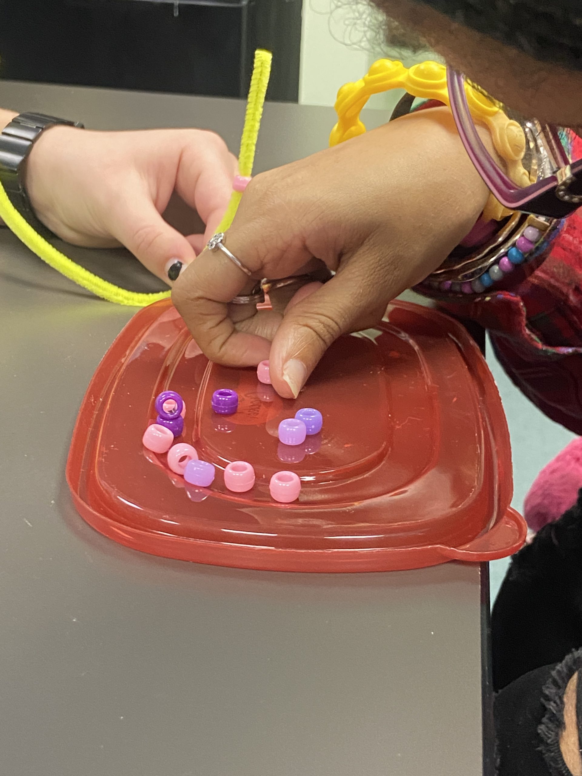
Darnisha demonstrating how she uses beads.
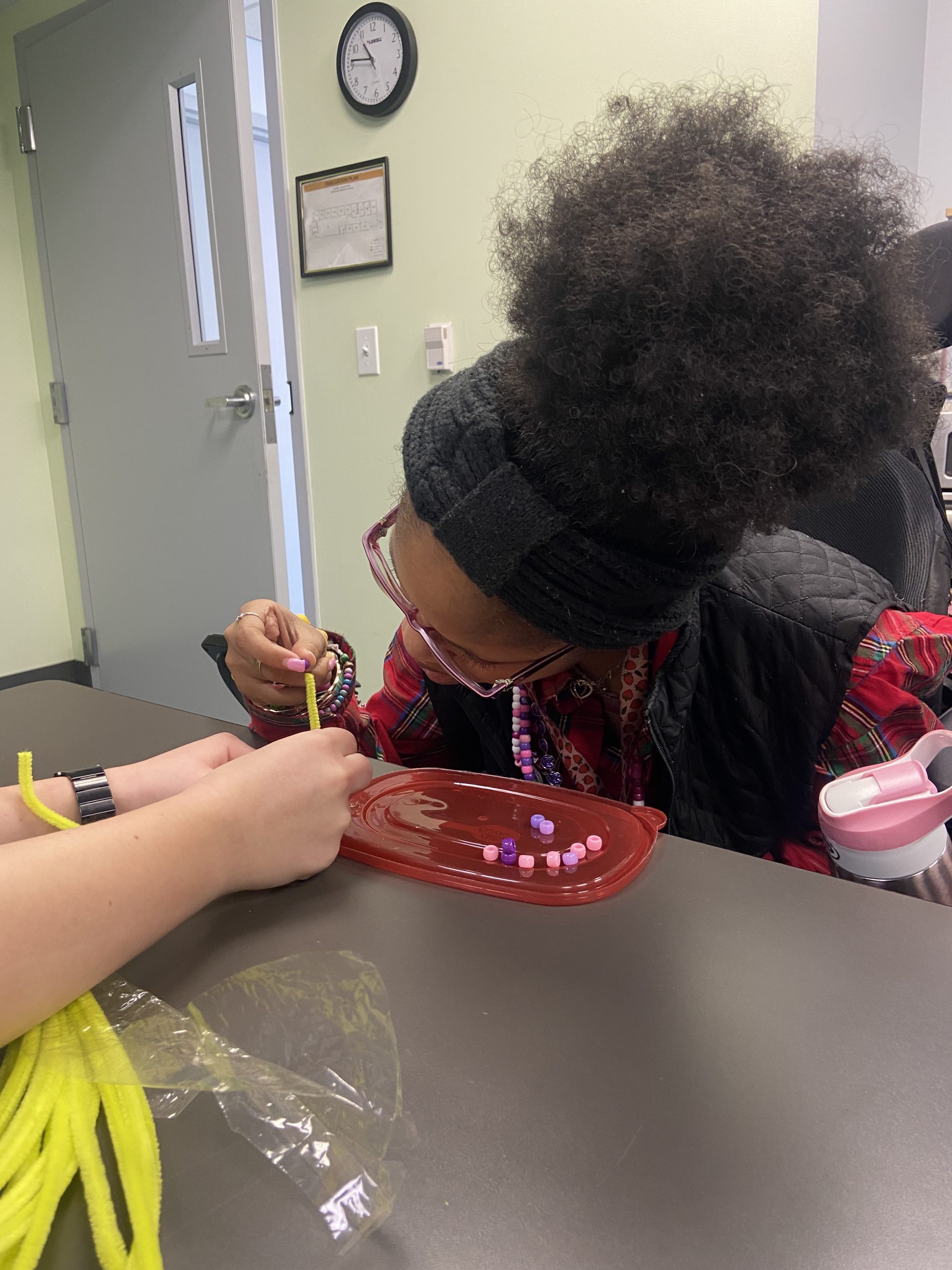
Darnisha stringing beads on a pipe cleaner.
Finally, we discussed some ways of input and output that she is comfortable with. She prefers light as an indicator. She mentioned that she can get startled easily, so it would probably be best to not use sound. She is used to switches and joysticks, and is comfortable with typing.
We left off with making sure that there weren’t any unanswered questions, and that we were all on the same page. As we left, Darnisha showed us one of her paintings of a beautiful ocean scene at night that was on display in the hallway.
Our thoughts after holding the meeting and discussing as a team:
Our meeting with Darnisha was great. We started off by introducing ourselves which perhaps built the conversation itself. The introductions led us into discussing our interests which made it easier for us to target areas of interest for Darnisha. Talking about and showing her our own previous projects also helped us explain the scope and context of the course, as well as this project, more clearly.
We followed our meeting agenda as our client was actually answering very to the point. Next time, we might want to ask additional follow up questions more related to her abilities as during the interview we might have spoken a lot about her interests and activities she might need help with, but we missed out on a couple of opportunities for her to engage physically with something. For example, Darnisha said that she is able to paint pretty independently, but it might’ve been beneficial to see her engage with a paint brush to see if we could make the process even easier for her.
We covered a good range with the questions we asked to Darnisha as they led from her daily routine to her interests, involving things she needs assistance with. As mentioned earlier, we could have asked her to engage more physically with things to help us know better about how she does those things in particular. As we did an activity with her about making a bracelet for her using beads and that gave us a good insight into her ability with her upper body and hands.
We as a group had a uniform opinion about the interview as we all had similar ways of questioning the client which made us realize we were actually targeting the same realm.
]]>Count by Hand! is a stitch and row counter for knitting and crocheting.
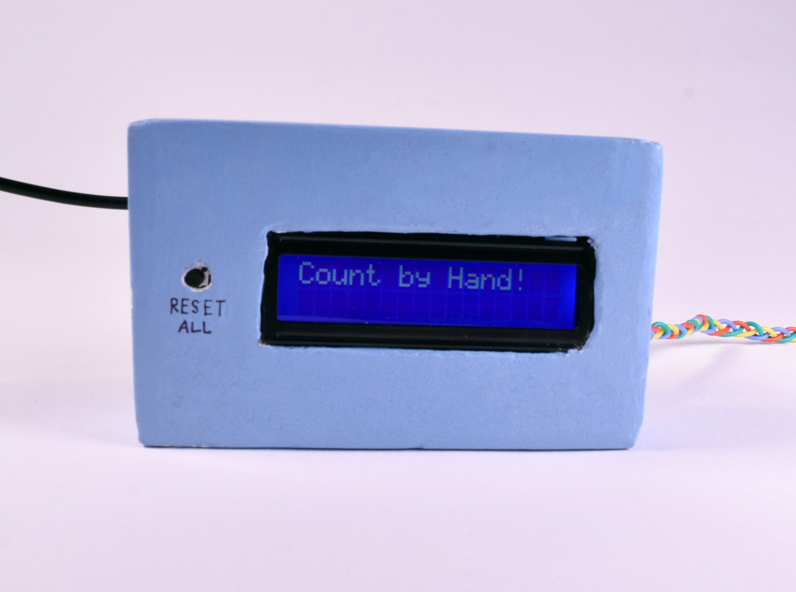
The Count by Hand! counter box. (approx. 4″ x 2.5″ x 1.75″)
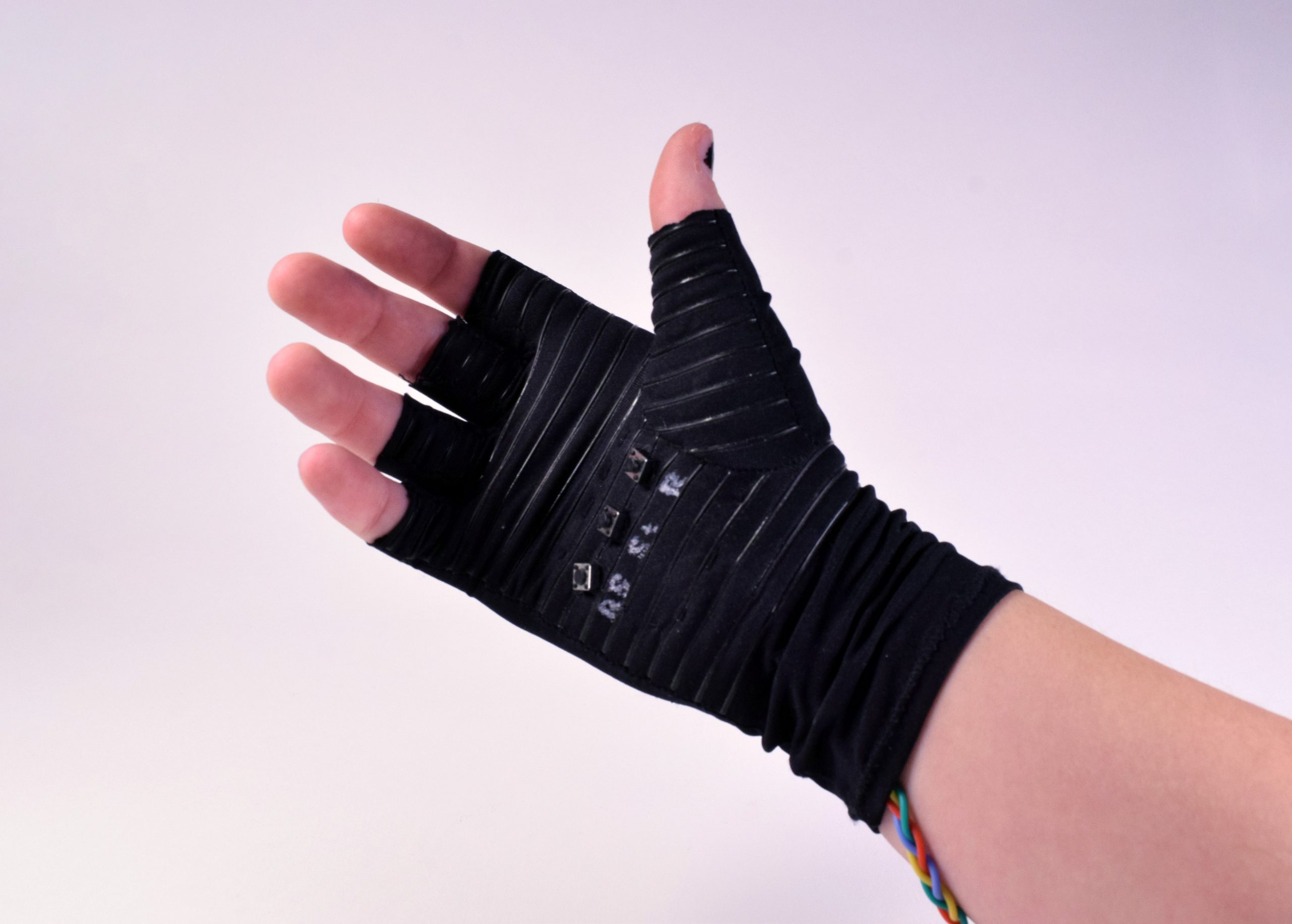
The glove with integrated buttons.
In action while knitting!
Process
In the beginning ideation phase, my initial idea was to have the counter be a part of a yarn bowl (a bowl that holds the yarn so it doesn’t roll around while you knit). When we talked with small groups about our idea, I talked with my group about how to make it easier to hit the buttons to add to the count. It was then that I decided to incorporate the buttons into a glove that would be right there on your hand.
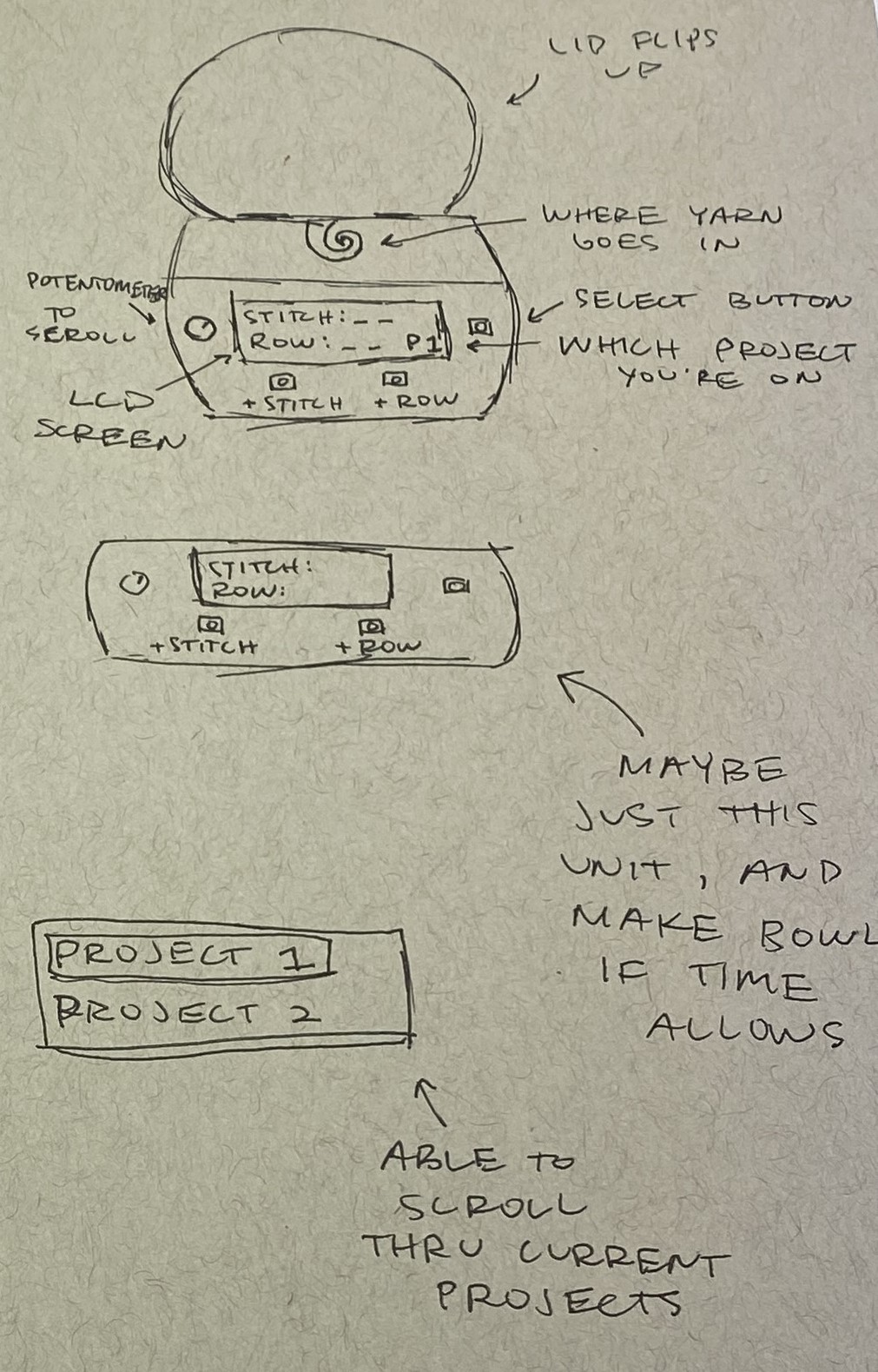
My initial sketch with the yarn bowl concept.
For the glove fabrication, I first soldered silicone coated wires to three tactile push buttons. Then I determined the placement of the buttons and cut very small holes in the glove. I mounted the buttons to a small piece of fabric stabilizer, then sewed the whole thing to the inside of the glove. The mechanics and wiring are all contained inside the stabilizer, so it is comfortable to the touch inside the glove.
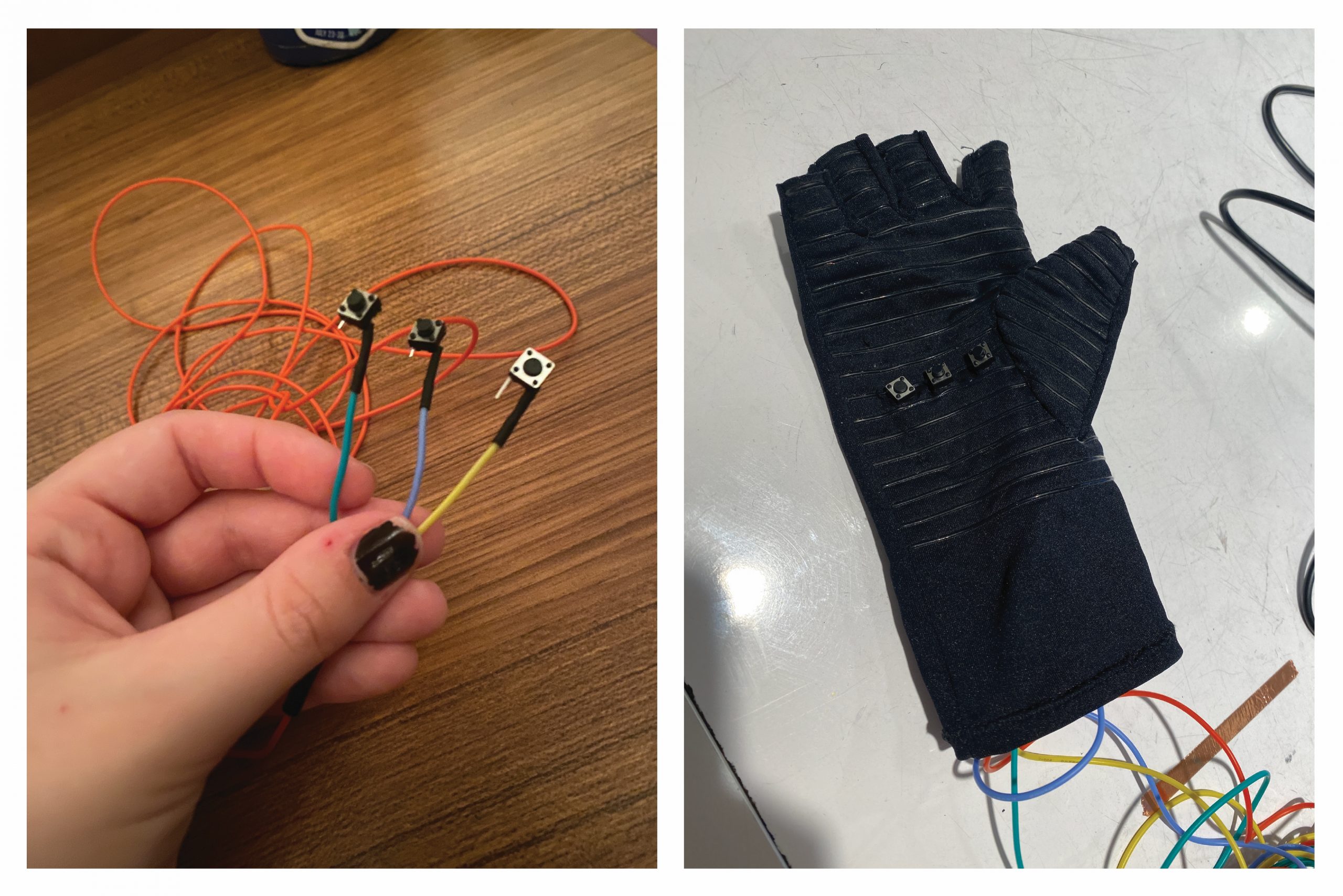
Glove fabrication!
I initially used a medium size breadboard just so I could figure out the connections for everything before making final decisions. I then realized that I wanted a smaller board so I could fit everything into a smaller container. This began the bread board saga. I first tried to switch everything over to a small breadboard. I then ran into issues with the power running the small one. I tried using a different small breadboard, but had the same results. I finally decided to just hack a medium breadboard in half with a saw in order to have a smaller overall size, but still be able to use the power rails on the board.
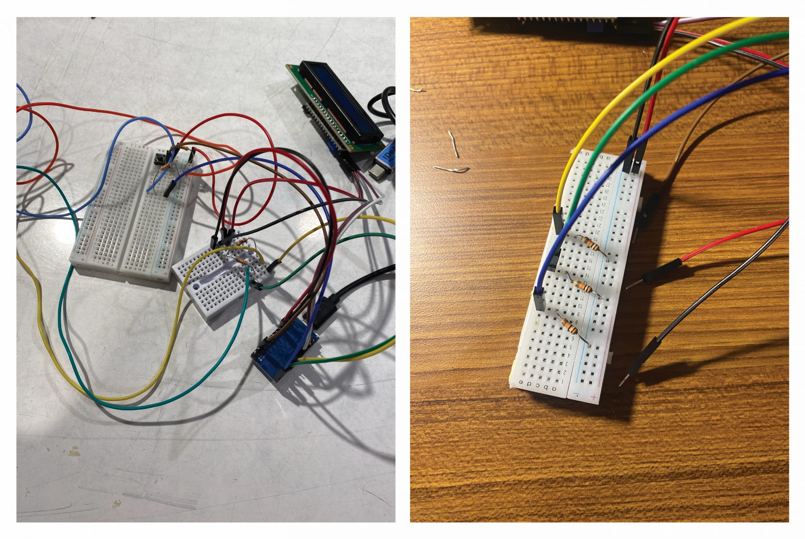
The breadboard saga!
I learned how to four strand braid to contain the wires from the glove to the box in a functional and beautiful way.
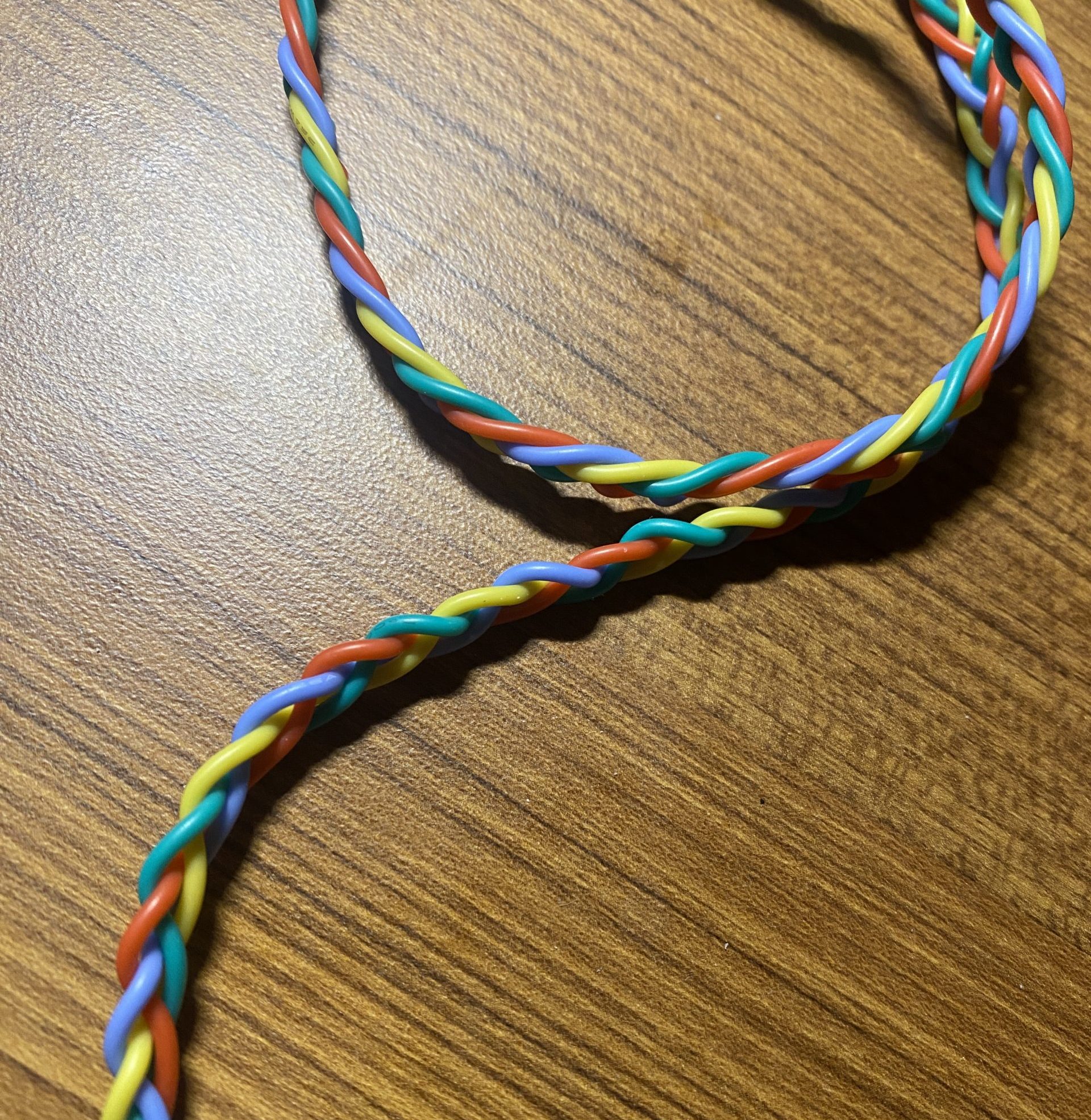
Four strand braid.
My friend trying to figure out how high the count could go – they gave up before they reached the max.
Discussion
I received some really helpful feedback from my peers in our final presentation. One person said that they “would like to see some user study info from [me] and other people to find the perfect button type and placement.” I totally agree with this – I would love to experiment more with the exact button placement on the glove for myself, as well as taking into account other fiber artists grips and styles of holding the tools. Finding a placement that could work well for a lot of different types of people would be a very exciting endeavor.
Another person asked if it was “possible for the buttons to activate without meaning to?” It’s pretty unlikely with the way the needles lay on my hand while I’m knitting, but it is certainly possible. I would love to add a function to undo or remove stitches without completely resetting the count in the future.
Overall, I’m pretty happy with how this project turned out. I’m very pleased with the electronic aspect of it – the functions that I was aiming for all turned out well. There are certainly more functions that I could add moving forward, but as far as the ones I included, they were very successful. The fabrication is definitely something that I would like to put more time and precision into in the future. I didn’t leave myself enough time for the fabrication, and so I rushed and cut corners a bit, then attempted to go back and fix those mistakes afterwards. I’d like to really take my time and be precise with my fabrication in the future.
I felt that I improved quite a bit on the electronics throughout this project. I’ve had very little experience in electronics and coding before this class, so I’ve definitely had a large learning curve. I liked the process of this project in that I had a problem to solve in my own life, and I had to figure out the specific functions that would solve it, rather than being assigned specific functions without much of a practical function like Project 1. It felt like there was more at stake here, and I enjoyed that. A fun little skill that I learned during this project was how to braid with four strands, which I used to braid the silicone wires that connected the glove to the counter.
If I were to take the project further, I would definitely focus on the fabrication more. I would like to streamline the design to be the most portable it could be, while still fitting all the components that it needs to. Additionally, I would like to add a function to adjust the count up and down to account for mistakes in addition to being able to reset the count totally.
Technical Information
Block diagram:

Schematic:

// Count by Hand: Keep track of your stitch and row counts!
// Mo Cambron

// Tactile push buttons sewed into a glove allow user to count the stitch
// and row count of a knitting/crochet project. 5V runs to three buttons,
// each button then runs back to Arduino Pro Micro. "St" adds to the stitch count.
// "Row" adds to the row count. "Res" resets the stitch count. Stitch and row count
// are displayed on an LCD screen. "Res" button next to LCD screen resets all counts.

// Pin mapping:
// - pin 5 = stitch reset button
// - pin 7 = stitch add button
// - pin 9 = row add button
// - pin 14 = total reset button


const int stRes = 5;
const int St = 7;
const int Row = 9;
const int Res = 14;

int stVal = 0;
int stPrev = 0;
int stCount = 1;
int stPress = 0;

int rowVal = 0;
int rowPrev = 0;
int rowCount = 1;
int rowPress = 0;

int stresVal=0;
int resVal=0;

const int stAddress = 0;
const int rowAddress = 5;


#include <Wire.h>
#include <LiquidCrystal_I2C.h>

#include <EEPROM.h>

LiquidCrystal_I2C screen(0x27, 16, 2);

void setup() {
  pinMode(stRes, INPUT);
  pinMode(St, INPUT);
  pinMode(Row, INPUT);

  Serial.begin(9600);

// LCD setup:
  screen.init();
  screen.backlight();
  screen.home();
  screen.print("Count by Hand!");
  delay(2000);
  screen.clear();

// Print "St=" and "Row=" on LCD
  screen.setCursor(0, 0);
  screen.print("St=");
  screen.setCursor(8, 0);
  screen.print("Row=");

// Get previous row and st counts for project
  EEPROM.get(stAddress,stPress);
  EEPROM.get(rowAddress,rowPress);
  stCount=stPress;
  rowCount=stPress;

// Print previous row and st counts onto LCD
  screen.setCursor(3, 0);
  screen.print(stPress);
  screen.setCursor(12, 0);
  screen.print(rowPress);
}

void loop() {

// St button read
  stPrev=stVal;
  stVal=digitalRead(St);
  if(stVal==HIGH && stPrev==LOW){
    stPress=stCount++;
    EEPROM.put(stAddress,stPress);
  }

// slight delay to account for bounce
  if(stVal==LOW && stPrev==HIGH){
    delay(20);
  }


// Row button read
  rowPrev=rowVal;
  rowVal=digitalRead(Row);
  if(rowVal==HIGH && rowPrev==LOW){
    rowPress=rowCount++;
    EEPROM.put(rowAddress,rowPress);
  }

// slight delay to account for bounce
  if(rowVal==LOW && rowPrev==HIGH){
    delay(20);
  }


// St reset button read
  stresVal=digitalRead(stRes);
  if(stresVal==HIGH){
    stPress=0;
    stVal=1;
    stCount=1;
    screen.setCursor(3,0);
    screen.print("    ");
  }

// Reset all
  resVal=digitalRead(Res);
  if(resVal==HIGH){
    stPress=0;
    stVal=1;
    stCount=1;
    rowPress=0;
    rowVal=1;
    rowCount=1;
    screen.setCursor(3,0);
    screen.print("    ");
    screen.setCursor(12,0);
    screen.print("    ");
  }

// Print current st count to LCD
  screen.setCursor(3,0);
  screen.print(stPress);

// Print current row count to LCD
  screen.setCursor(12,0);
  screen.print(rowPress);
}
]]>