Special Effects Automation Kit
The special materials for the course include a rapid-prototyping kit of laser-cut wood parts and standard mechanical components. This is intended to ease building articulated armatures with a minimum of fabrication. The individual component designs are all available as a start for projects to make custom parts, subject to CAD and laser-cutter experience.
The course emphasizes real-time practical effects, mostly at model-scale. Since this usually happens on a shot-by-shot basis, the goal is to support quick, temporary construction, and to keep it very inexpensive. This is likely to include the following needs:
- building structures to hold materials in a scene
- making articulated armatures to move props or puppets in a scene
- setting up rigs to hold or move lights and cameras
- connecting actuators to rigs and armatures for scene automation
The following guide includes images of the reference designs. Many of the parts exist in multiple variations which can be found in the DXF file archive. These images are not to scale.
Contents
Overview
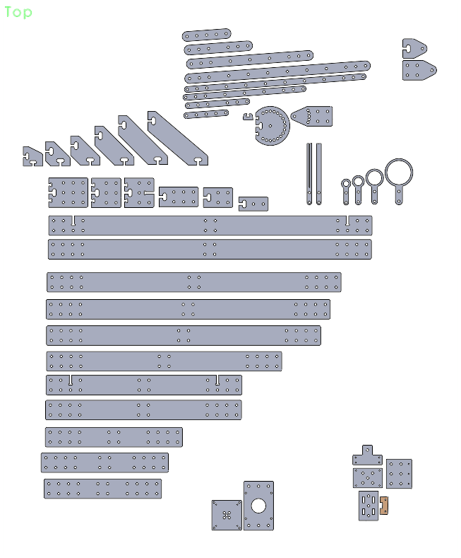
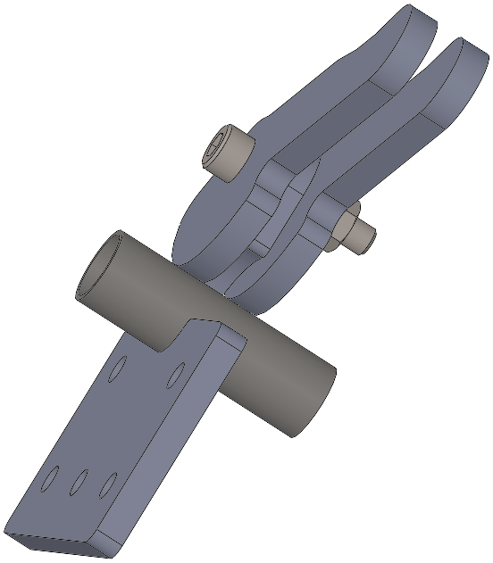
Reference demo layout for most of the laser-cuttable parts in the kit. This shows many of the variations for each basic part.
Structural Parts
Optical Breadboard
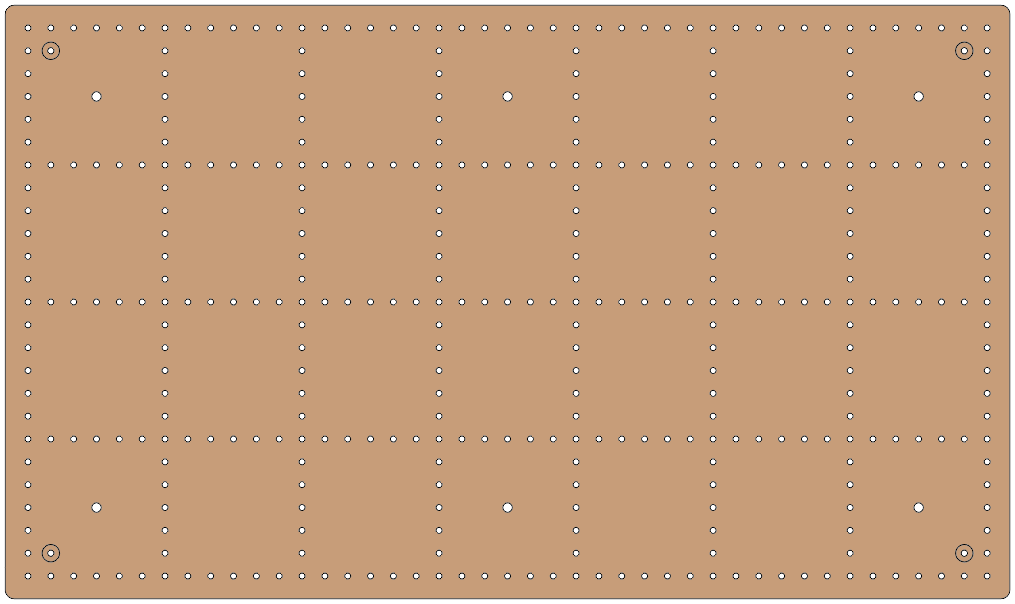
Large multi-purpose base plate for assembling a tabletop scene. CNC-cut from 12mm plywood.
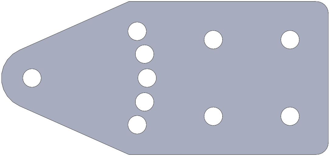
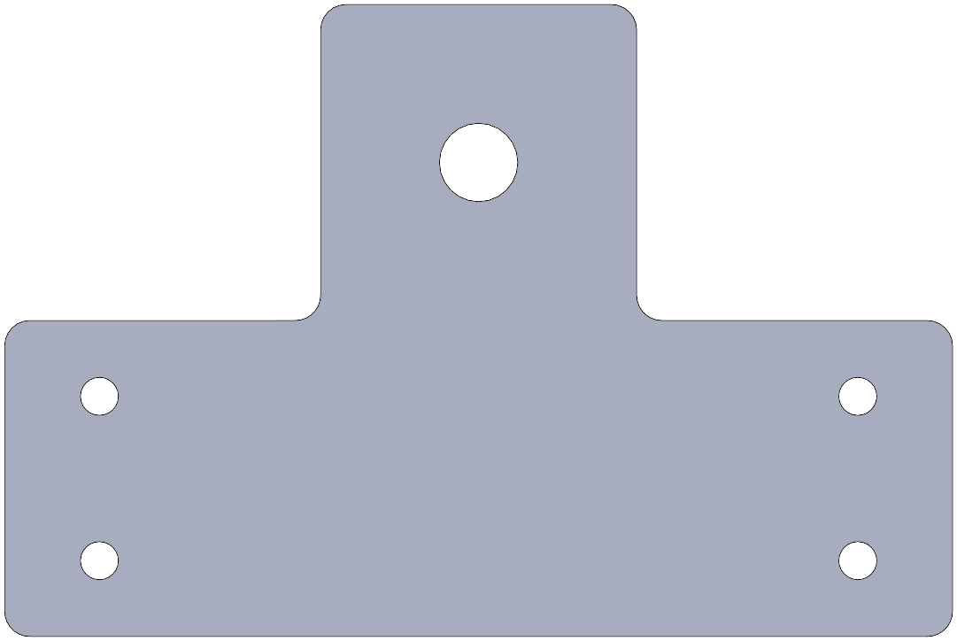
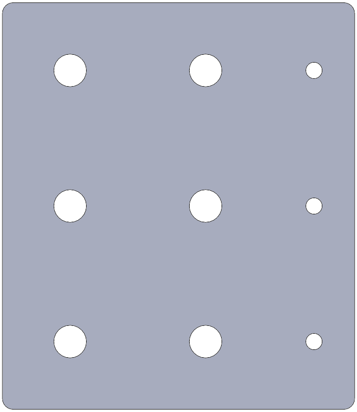
Structural Links
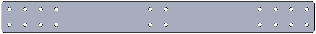
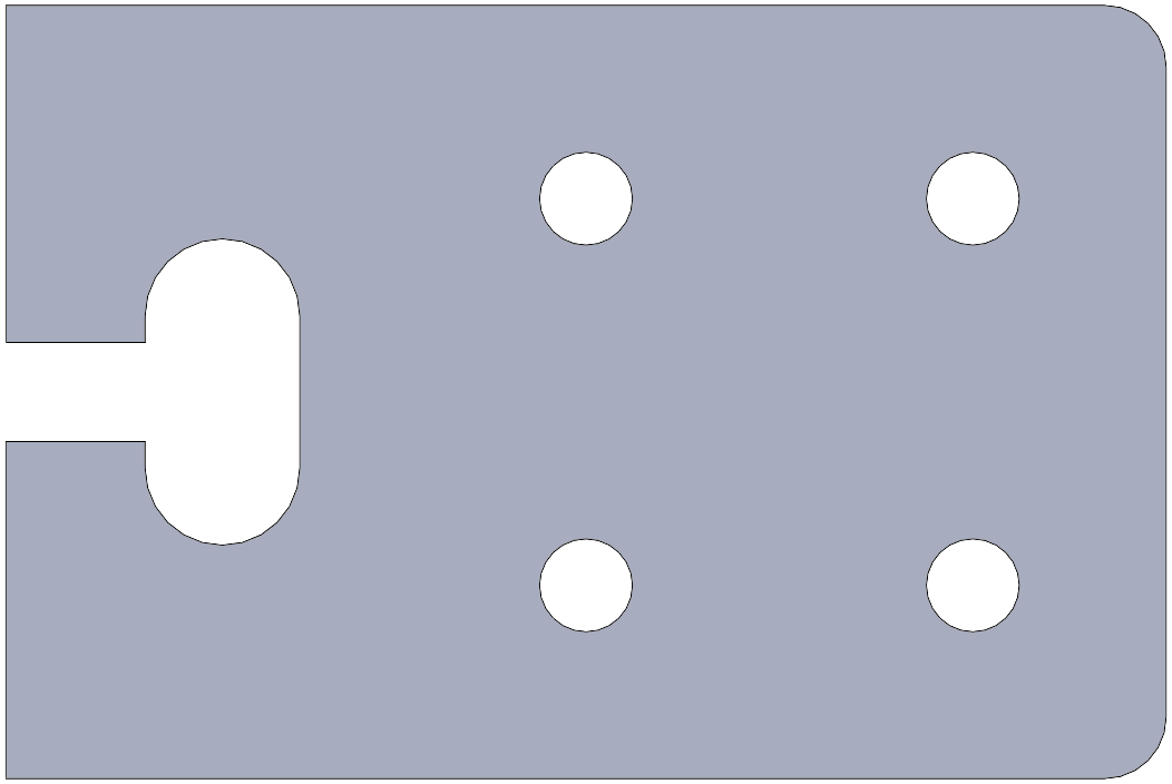
General-purpose wide flat link with standard hole patterns for building rigid structures. Available in multiple lengths, with or without lap-joint slots.
Armature Links
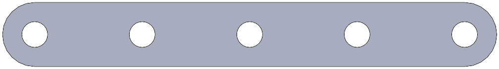
General-purpose narrow flat link with standard hole patterns for constructing linkages and armatures. Available in multiple lengths.
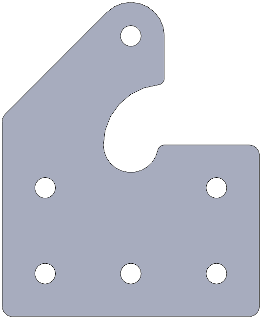
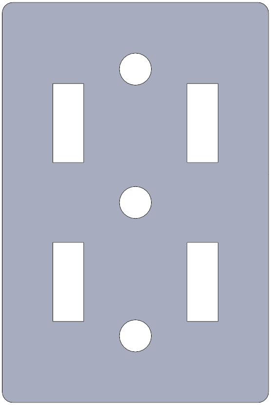
Vertical Flange
General-purpose mounting plate with standard hole pattern which attaches perpendicular to a surface. Available in multiple sizes.
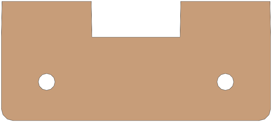
Diagonal Brace
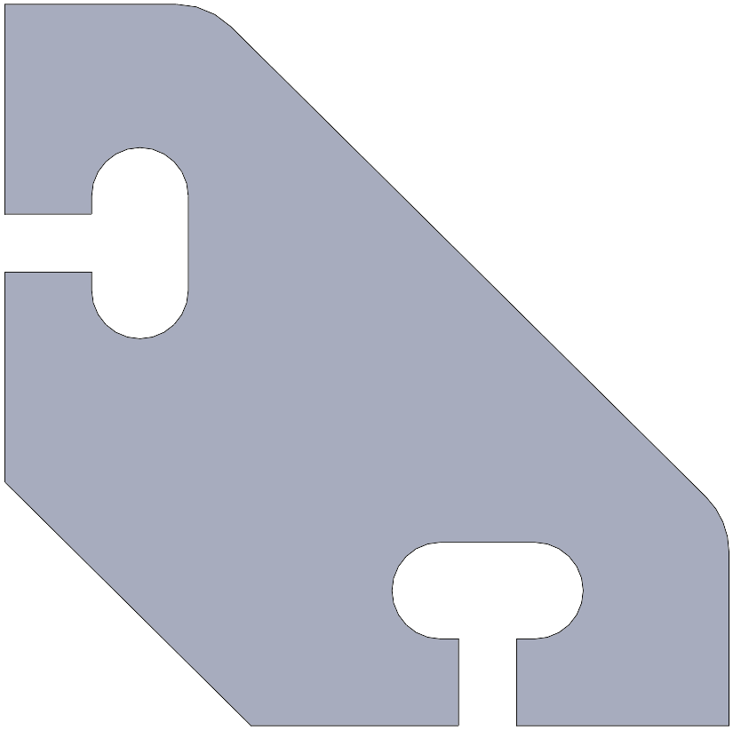
Provides two captive-screw connections at a right angle. Available in multiple sizes. Useful for attaching structure links perpendicular to the table.
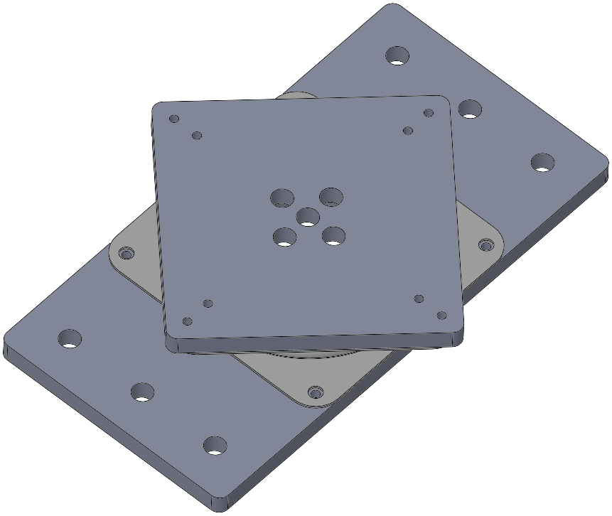
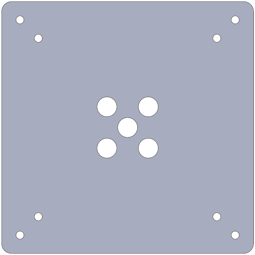
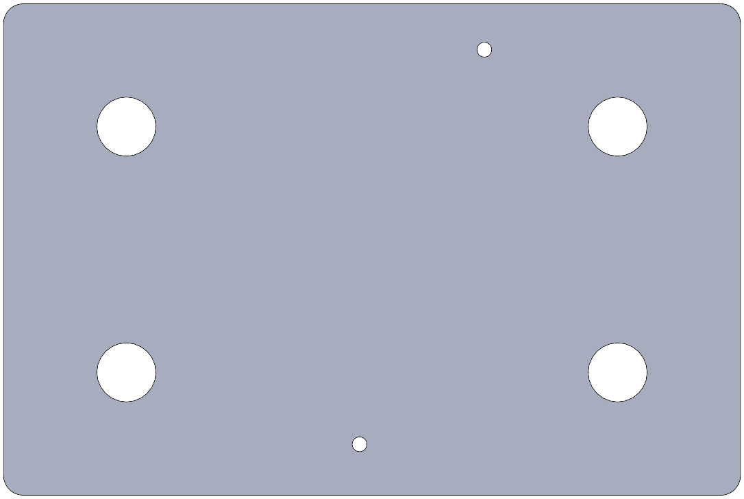
Grid Plate
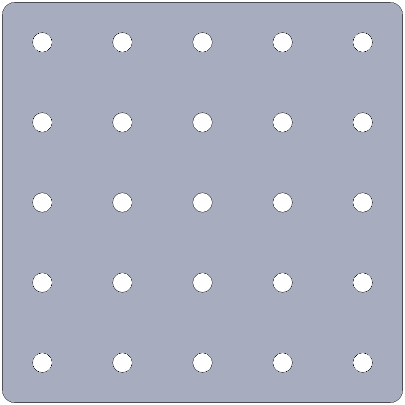
General-purpose adapter plate with a standard hole pattern, available in many sizes. May be used as a secondary table, an armature base, turntable extension, etc.
Tubing Clamp
General-purpose adapter plate which can cam-lock onto a round tube. Available in several sizes for different lighting-stand section diameters. May be used as light anchor, gobo mount, motor mount, etc.
Precision Angle Mount
Base with pivot and coarse-adjustment pin holes for supporting bracket at precise angles with 3 degree resolution.
Pivoting base with fine-adjustment pin holes for installing at precise angles. The holes have a different pitch than the base to subdivide each coarse interval in the style of a vernier scale.
Rotating Joints and Articulations
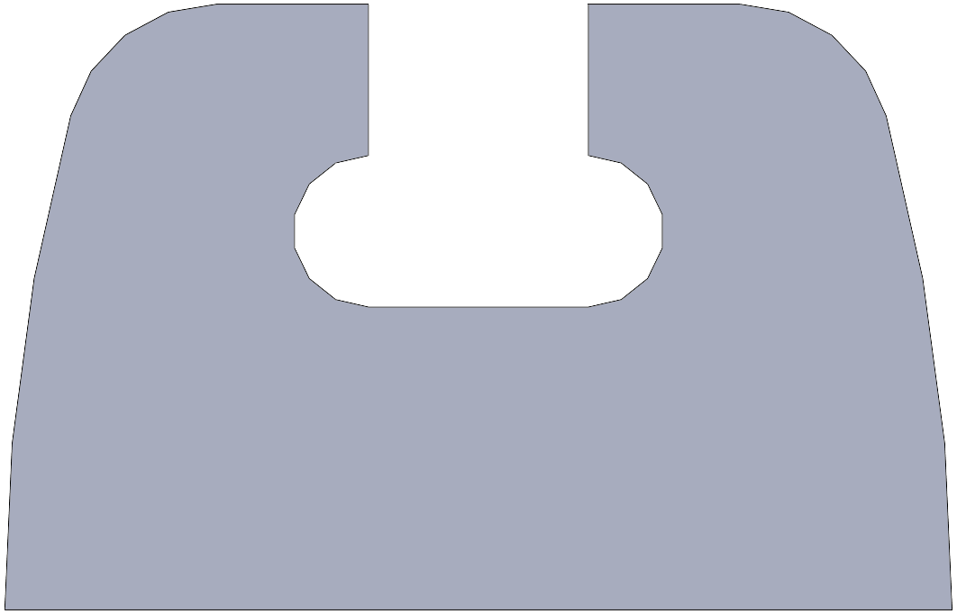
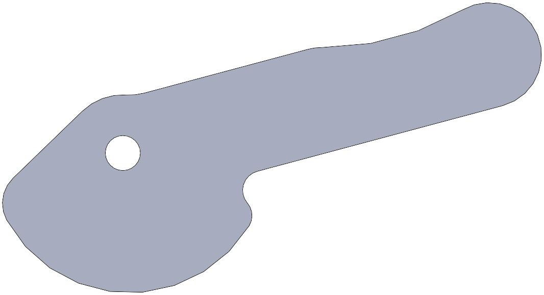
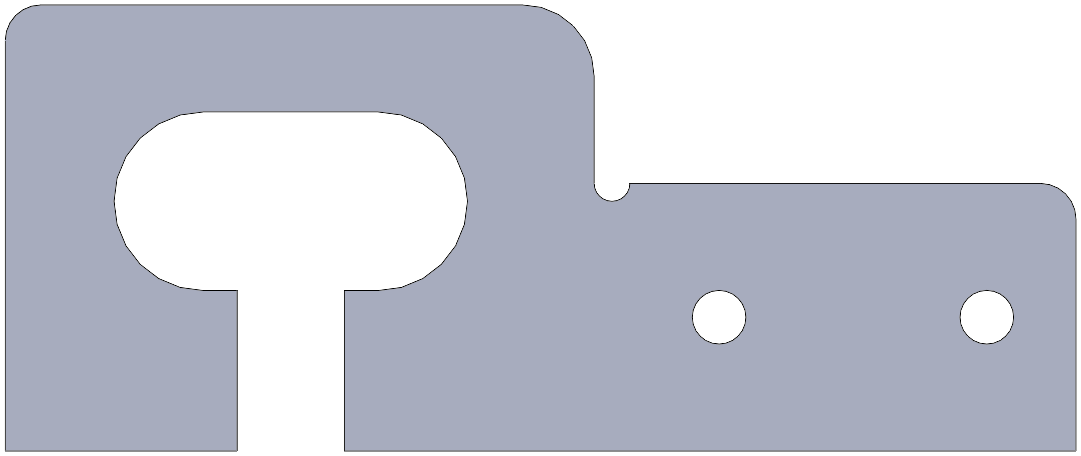
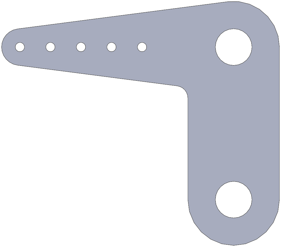
Offset-Pivot Plate
One-half of a pivot joint (e.g. elbow). Can also be used in pairs to form a clevis, or to mount a camera using the pivot hole. Available with either a captive-screw connection or a hole pattern.
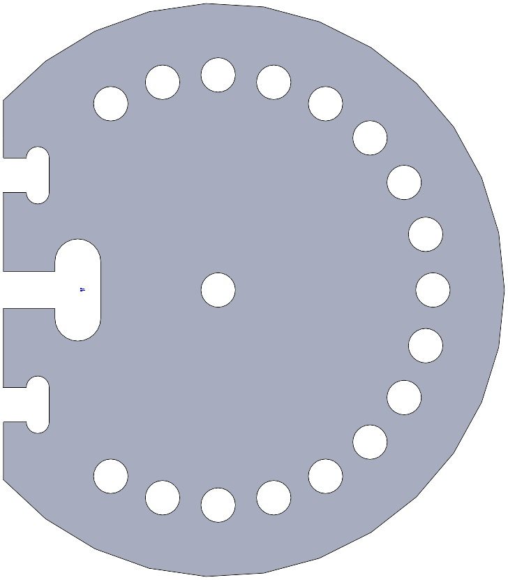
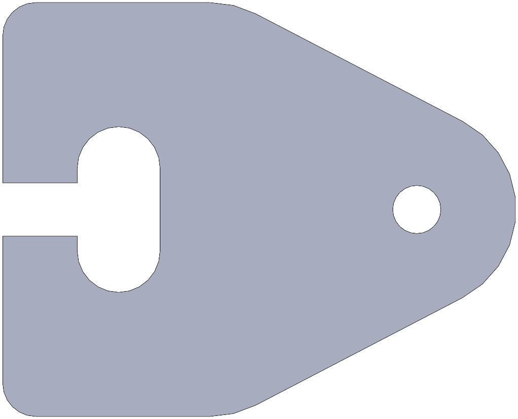
Lazy-Susan Turntable
A turntable built around a standard ball bearing lazy susan component, commonly fixed to a table as a base joint.
Adapter plate for mounting the turntable component. Available in several shapes and hole patterns. The 6 mm plywood plate can be screwed to the metal turntable component using #6 x 1/4 inch rounded-head sheet metal screws.
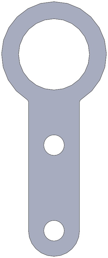
Fixed Ball Joint
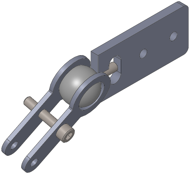
An adjustable fixed ball joint, commonly used for hand-animated armatures. The ball is a standard component.

One-half of the clevis supporting the ball in a ball joint.
Flexure Link
Experimental flexure joint. The movement is similar to a pin joint with a light centering spring, but the axis of rotation isn’t fixed.
Linear Joints
Sliding Rail System
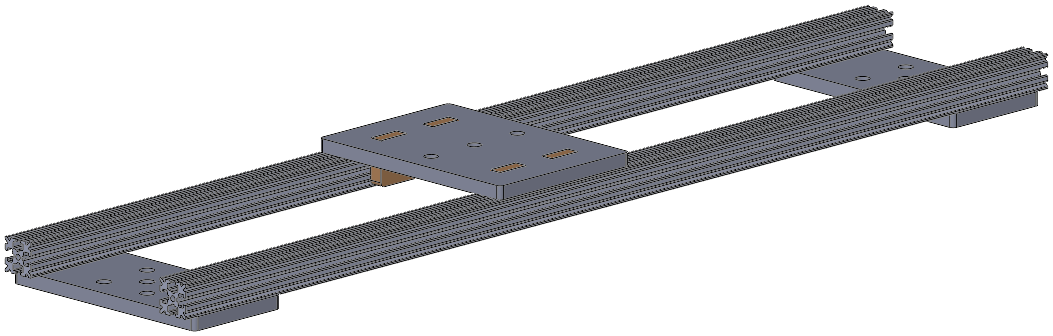
A single-axis translation joint using a wooden sled sliding on 15mm aluminum extrusion.
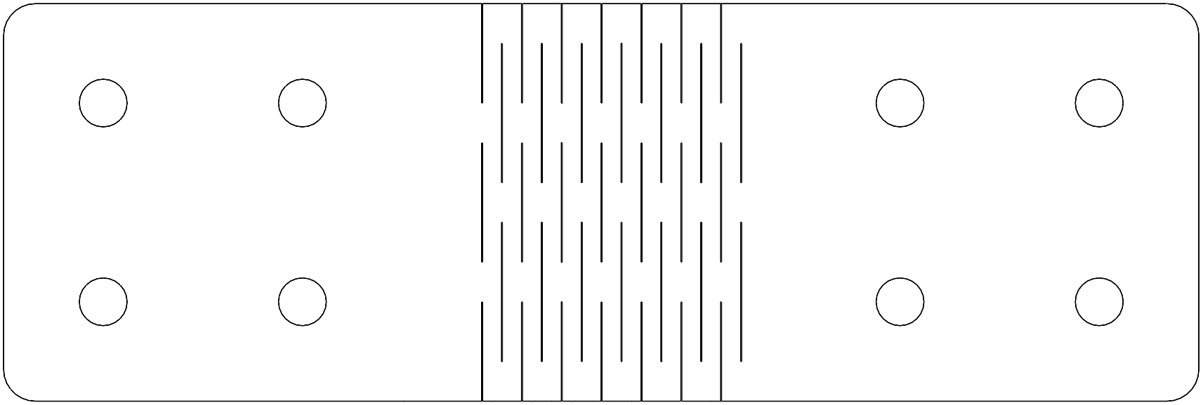
Rail Tie Plates
Connector for holding two 15 mm extrusions parallel to serve as slider rails. Provides a standard M6 pattern and M3 holes for screws to fit the extrusion slots.
Alternate connector for attaching 15 mm extrusions into rail structures.
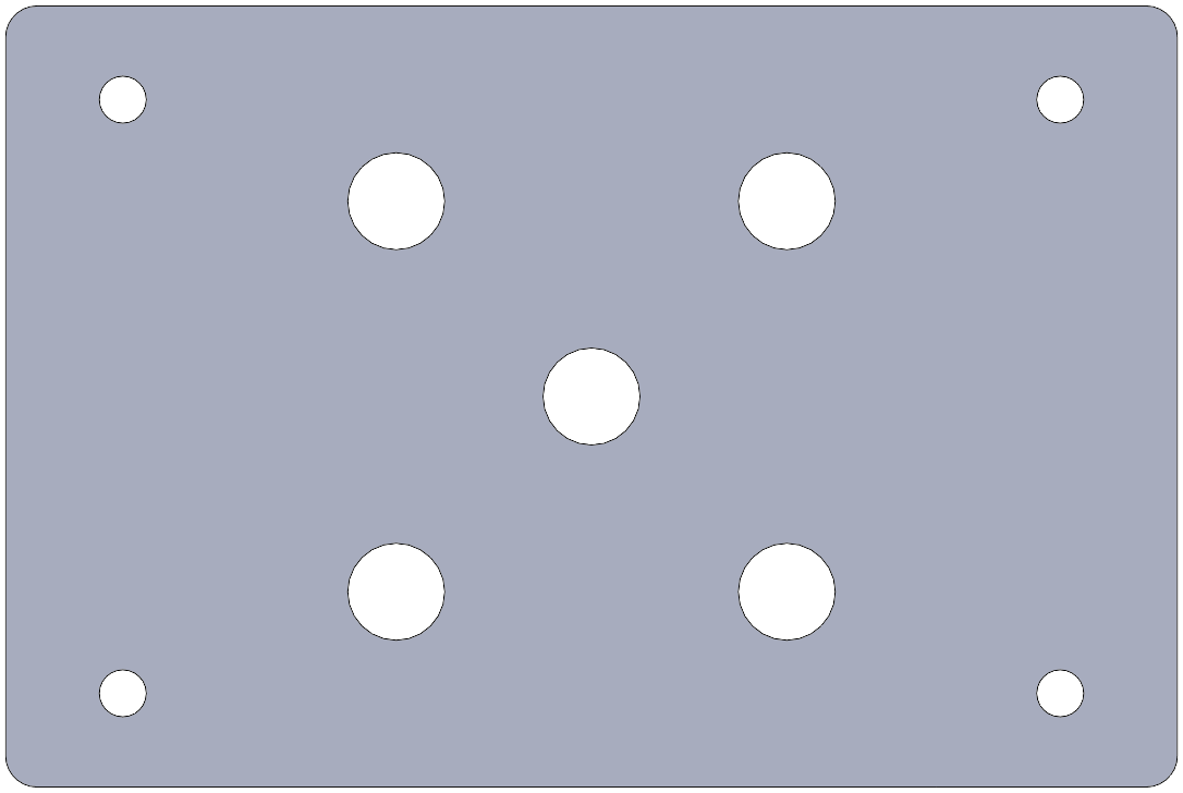
Rail Slider
Top plate for a simple sliding base which can move along a pair of 15 mm extrusion rails. Available for several track widths.
Guide plate for the simple sliding base which slots into the top plate.
Extrusion Clamp
Adapter for mounting a single 15 mm extrusion rail flat against the table. Provides a captive-screw connection and holes for M3 screws to anchor in an extrusion side slot.
Extrusion Adapter
Adapter for fixed mounting to a 15 mm extrusion rail. Provides a standard M6 hole pattern and holes for M3 screws to anchor in an extrusion slot.
Actuation
Vertical Servo Mount

Mounting plate for a single hobby servo. Available in several sizes for specific servos, which all have slightly varying mounting patterns.
Mini-Maestro 18 Mount
Mounting plate for supporting a Mini Maestro 18 servo driver circuit board. It is recommended to anchor the driver circuit board to the table using this plate to avoid shorting out any connections; there will be many servo wires pulling on it, and the back has un-insulated points.
Multi-Micro-Servo Mount

Mounting plate for six micro-servos.
Pushrod Horn
Adapter for connecting pushrods to wooden structures. Available in multiple angles and sizes.
Accessories
Flat Element Holders

Fork-shaped clip for holding a lightweight optical element such as a piece of gel. Has a stub end to press-fit into a 6mm hole. Available in several slot widths.

Fork-shaped clip for holding a lightweight optical element such as a piece of gel. Has a standard M6 hole pattern. Available in several slot widths.
Lens Holder
Holder for a round glass lens. Available in multiple sizes.
Gears
Spur Gear
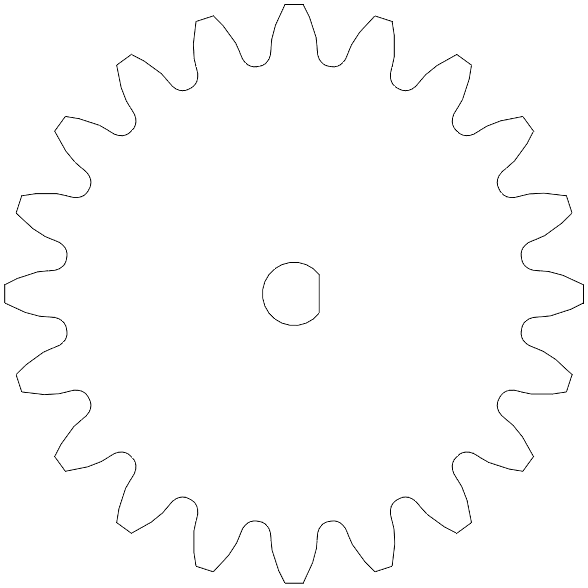
Spur gear, 2 mm module, 20 degree pressure angle. Available in multiple sizes and several bore shapes. With a 2 mm module, the pitch radius is the same as the number of teeth.

Basic Connections
(need sketch or photos for: captive-screw connection, standard hole pattern, lap-joint slot, etc.)
Standard Components
(need renderings or images for shoulder screws, servos, bearings, etc.)
License and Repository

The text content and mechanical designs of the 16-374/60-428 Automation Kit by Garth Zeglin are licensed under a Creative Commons Attribution-ShareAlike 4.0 International License. Based on a work at https://courses.ideate.cmu.edu/16-374.
The original SolidWorks design files for the wooden components are available as a single zip file, or may be browsed file by file in the SolidWorks file tree.
Design Rule Guide
The base components and subassemblies were designed with the following set of constraints, chosen for both general purpose utility and simplicity of fabrication. New parts for the kit should generally follow this rules. This list will continue to evolve.
- Material: 6 mm Baltic Birch double-sided plywood.
- Dimensional grid: part features are generally chosen on a 25mm grid. E.g, the basic straight connecting links are 25 or 50mm wide.
- Wooden part fasteners: M6 bolts and nuts. Specific components may require special cases.
- Extrusion rail fasteners: M3 button-head socket cap screws and square nuts.
- Clearance holes: nominal 6 mm. This is a close fit on an M6 screw.
- Bolt pattern: the standard interconnection pattern uses a 25 mm grid with four 6 mm holes at the vertices of a square with 25 mm sides, centered in a 50 mm square area.
- Shafts: 6 mm shoulder screws.
- Shaft holes: 6 mm drill. This is a free fit on a 6 mm shoulder screw. (This may need adjustment.)
- Where parts glue together, provide 0.2 mm glue gap: increase holes in outer surfaces by 0.4 mm diameter, increase slot lengths and widths by 0.4 mm.
- Existing tabs are either 15 or 30 mm long. Existing slots are 9.4 mm wide and 15.4 mm or 30.4 long with the glue allowance. Inside corners are 3.5 mm radius. The preferred inside corner design uses a 180 degree arc, but the position varies depending on the purpose.
- Bearings: still in flux. Some components will use a 6 mm shaft in a plain wooden hole, some may use a 6 mm shaft in a bushing with 8 mm OD, some may use an 8 mm shaft in a 8x22x7 mm skate ball bearing. The actuated knee designs use a 50x65x7 mm thin-section ball bearing.
- SolidWorks parts include Design Tables wherever possible with systematic parametric variations.