Mini-Maestro Servo Interface
The Mini Maestro 18-Channel USB Servo Controller from Pololu is a USB interface for driving up to 18 servos or digital I/O lines from a computer. It is also available in several other sizes.
Diagram
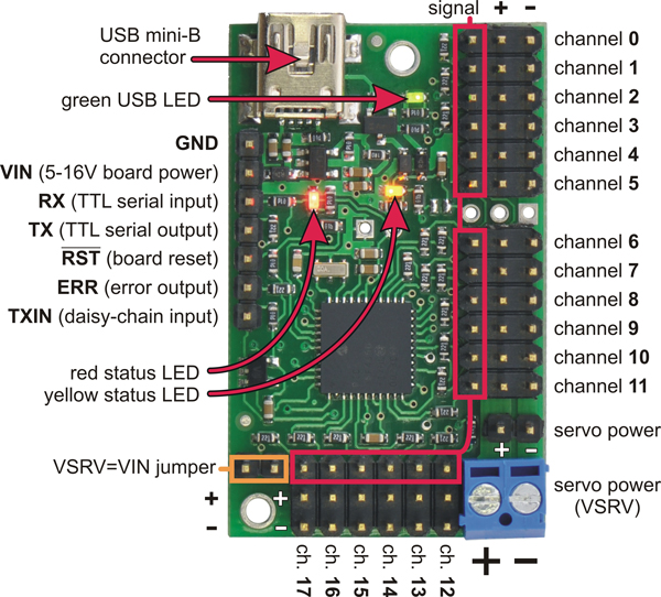
Mini Maestro 18-channel USB servo controller, labeled top view. (The original image can be found on the Pololu product page.)
Power
The board draws power for computing from USB, but the motor power must be supplied externally. For class we have 5V@5A power supplies with a 5.5x2.1mm barrel jack (center-positive), connected using a screw-terminal adapter. The default wiring uses short lengths of wire between the onboard terminal strip and the adapter. Please handle the boards carefully to avoid pulling out these wires. It is crucial that this wiring not be reversed, and that the correct supply is used; we will also have 12V supplies for stepper motors, and these must not be used.
Mounting
By default we use two plastic 2mm screws to anchor the board to a rectangle of plywood. Please use the holes in the plywood both to securely anchor the board to your structure, and to strain-relief the USB and power supply wiring using wire ties.
Initial Setup
We have pre-configured the boards for class, but if you are buying your own hardware you may need to configure it.
The Mini Maestro board should be configured using the Pololu-supplied Maestro Control Center configuration program (Windows or Linux) as follows. Note that this utility can save and load all settings to a file, which eases configuring multiple boards identically.
- First verify that firmware 1.03 or later is installed in order to work with macOS 10.11. New firmware files can be downloaded from the Pololu site; be sure to get the proper version for the specific board model; see the Upgrading Firmware section of the manual for details and links.
- Serial set to USB Dual Port mode.
- CRC should be left disabled.
- Servo timing ranges should generally be increased to enable full servo travel. Our defaults are 608 usec min, 3008 usec max.
Mini Maestro Commands
The Mini Maestro uses a binary serial protocol to receive commands and report status. The details are documented in the online Maestro User’s Guide.
The two essential commands we use from the protocol are as follows. The data follows a convention in which initial command bytes have the most-significant bit set, then subsequent data bytes contain seven-bit values with the MSB clear. Values larger than seven bits are divided into seven-bit words.
Set Target command: 0x84, channel, pulsewidth-low-7-bits, pulsewidth-high-7-bits
This command updates a single servo output. The channel value designates the hardware output, starting with zero. The 14-bit data value is the desired pulse width in units of 250 nanoseconds.
Example: setting channel 2 to 1500 microsecond pulsewidth. This has the pulsewidth value 6000 (0x1770). The lower seven bits of this value are 0x70, and the upper seven bits are 0x2e, so updating channel 2 would be encoded as the four bytes [0x84, 0x02, 0x70, 0x2e].
Set Multiple Targets command: 0x9f, number-of-targets, first-channel, low-7-bits-0, high-7-bits-0, low-7-bits-1, high-7-bits-1, ...
This command simultaneously updates multiple outputs.