Tutorial: Stepper Motor Motion
This tutorial will introduce the use of stepper motors for creating precision movements with long travel. Stepper motors have multiple drive coils and a magnet structure which allow them to move in fixed increments. A common step angle geometry is 1.8 degrees, i.e. 200 steps per revolution. Moving a stepper requires a two-channel bidirectional driver. The A4988 drivers we use can also microstep by applying PWM to each coil to produce up to 16 intermediate positions.
Steppers are open-loop devices (no feedback), so maintaining precise operation depends on not overcoming the drive torque. If a stepper motor is stalled or accelerated too quickly, the driver will cycle the currents without shaft motion, and the system will lose count.
Likewise, there is no absolute position reference: a stepper system can only count relative movement. If absolute positioning is required, the system must either be started in a known location or a homing switch introduced to sense a reference position.
Contents
Objectives
At the end, you should be able to do the following:
- design a simple scene in which one or two elements can be automated using a stepper motor
- compose a motion program in G-code
The result is otherwise open-ended: you may shoot live or use stop-motion, etc. This is a good opportunity to explore some aspect of your first group project, e.g., by attempting to create a purely abstract visual using just a programmed turntable with optical elements.
Deliverables: please finish setting up your scene and shoot a short video (e.g. 10 seconds) using a lab Sony a6000. The video should be uploaded to Vimeo and embedded in a short blog post. Please assign all group members as authors on the post. This is due Monday at 5PM.
CNC Shield and grbl
We will be using the grbl firmware for Arduino CNC motion to drive a system with up to three stepper motors. This firmware is commonly used to drive three-axis machining tools using G-code. It is not specifically written for animation, but is a robust system for controlling coordinated movement using a standard text-based command language.
The electronics comprises an Arduino and a CNC Arduino Shield which in turn carries three Pololu A4988 stepper driver modules. The Arduino has been pre-programmed with grbl and the A4988 modules pre-configured for our steppers, so there should be no need to go through the installation and setup instructions unless you are buying your own equipment.
The CNC package needs to be connected to a computer via USB, a 12V power supply, and up to three stepper motors. Please be extra careful not to attach the 12V supply to any of the 5V Mini Maestro which we are also using. You would likely destroy the Maestro. Images of a typical installation can be found on the CNC Arduino Shield page.
Stepper Motor Turntable
We are providing components for driving a lazy-susan turntable from a stepper motor:
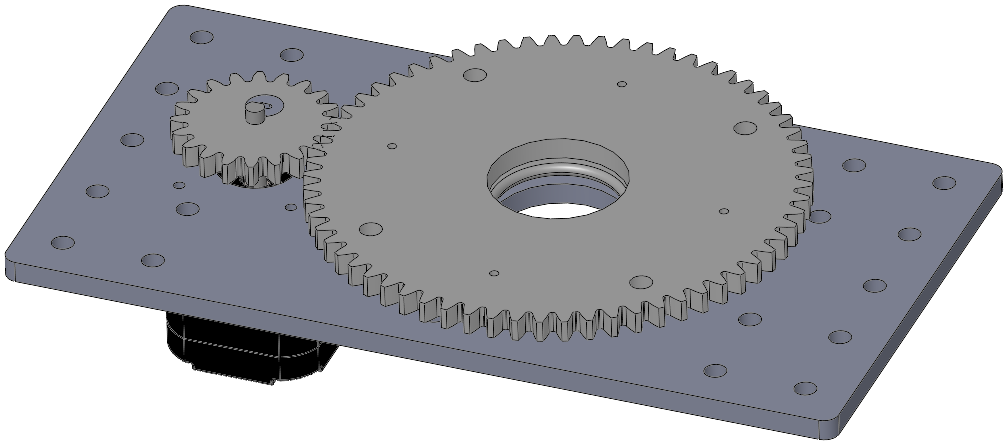
This structure uses the following wooden parts:
- turntable-base.DXF
- pan-spur-gear-64-tooth.DXF
- pinion-spur-gear-20-tooth.DXF
- pinion-spur-gear-key.DXF
The lazy-susan bearing attaches between the base plate and the large spur gear using the small sheet-metal screws in the lab. The recommended order is to screw it to the base plate first; there are access holes in the plate to ease installing the screws into the gear.
The pinion gear is clamped to the stepper motor shaft using a small eccentric key, which may be rotated with a screwdriver into a position pressing against the shaft flat.
You may wish to attach normal right-angle plates as feet, or bolt the baseplate to an optical breadboard, at your discretion.
Stepper Motor Programming in Max
Getting Started
- Download and unpack stepper-tutorial.zip. You should now have a folder named
stepper-tutorialwith several files. - Load the
stepper-tutorial.maxpatpatcher into Max. - Try entering a single G-code command, e.g.
G0 X12. - Try enabling auto-step and running the sequencer. The commands for the
sequence were loaded from
gcode-sequence.txt.
Rotational Units and Speeds
The motor itself operates at 3200 microsteps per revolution: the drivers are configured for 1/16 microstepping, and the motors are 200 steps per revolution.
The turntable drive gear ratio is 20:64, introducing a 3.2:1 speed reduction, for a total count of 10240 microsteps per turntable revolution.
The default grbl parameters assume 250 microsteps/distance unit. Combining these values yields 40.96 units per turntable revolution.
The default grbl parameters assume a maximum speed of 500 units/minute, which is relatively slow: at max speed, the turntable takes about 5 seconds per revolution, or 12 rpm. If this is too slow, the firmware limits can be updated in EEPROM using special commands, as shown in the following section.
Configuring Grbl Units
If you wish to work in real units, the scaling factor can be adjusted for the specific hardware, as per the following examples.
Turntable in Degrees. As discussed above, the net effect of the turntable gearing produces 10240 microsteps/revolution, so the desired scaling factor is 10240 microsteps/360 degrees, which reduces to 28.444 microsteps/degree. However, the maximum speed, acceleration, and travel limits also need to be adjusted since they will also now be specified in degree units. Reasonable values might be a maximum speed of 10800 degrees/minute (i.e. 180 degrees/second, or 2 RPM), an acceleration of 90 degrees/sec/sec (i.e. two seconds to achieve top speed), and a max travel of 3600 degrees. Assuming you have the turntable stepper connected to axis X, the following special commands can be issued once to persistently set the motion parameters in EEPROM. This can be performed using the single-line command prompt in the Max patch or using a separate terminal program:
$100=28.444
$110=10800
$120=90
$130=3600
Linear Slide in Millimeters. The slider track uses a pinion gear with 14 teeth and a 2 mm modulus. The pitch circle thus has a diameter of 28 mm and a circumference of 28*pi millimeters. One pinion gear rotation with 3200 microsteps thus yields 28*pi millimeters of linear travel, so the scaling factor is 3200/(28*pi), which is 36.378 microsteps/mm. Reasonable parameter values for this device might be a maximum speed of 6000 mm/min (i.e. 100 mm/sec), acceleration of 100 mm/sec/sec, and a travel limit corresponding to your track length. Assuming you have the slide attached to axis Y, the following special commands can be issued once to persistently set the motion parameters:
$101=36.378
$111=6000
$121=100
$131=280
Reference: Configuring-Grbl-v0.9