Ovalight
Final Documentation
Jasper Krarup | Gates Project | Fall 2022 | 62-362

Narrative Description
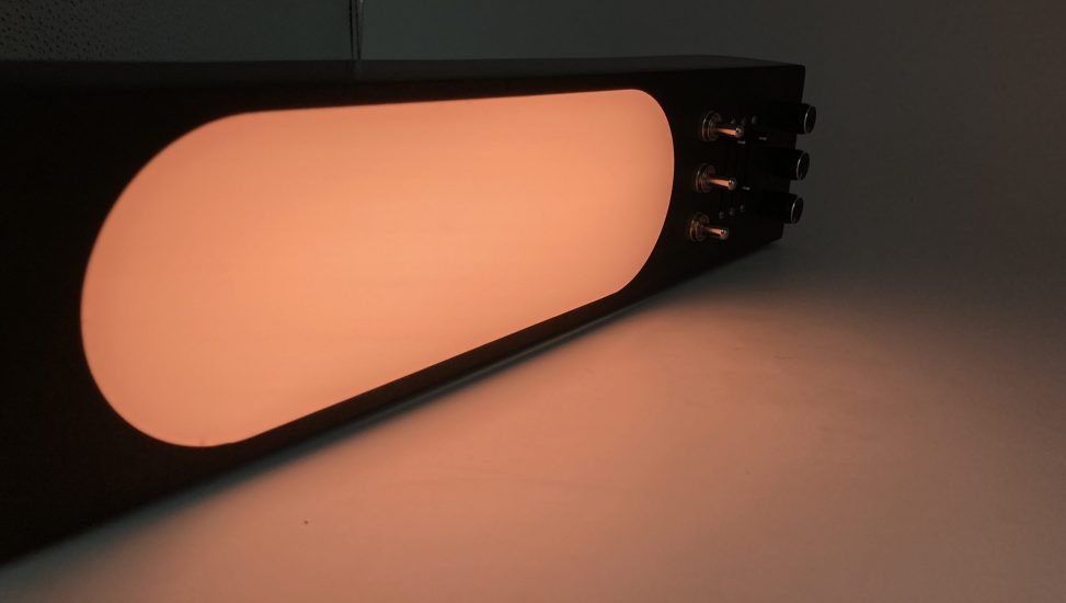
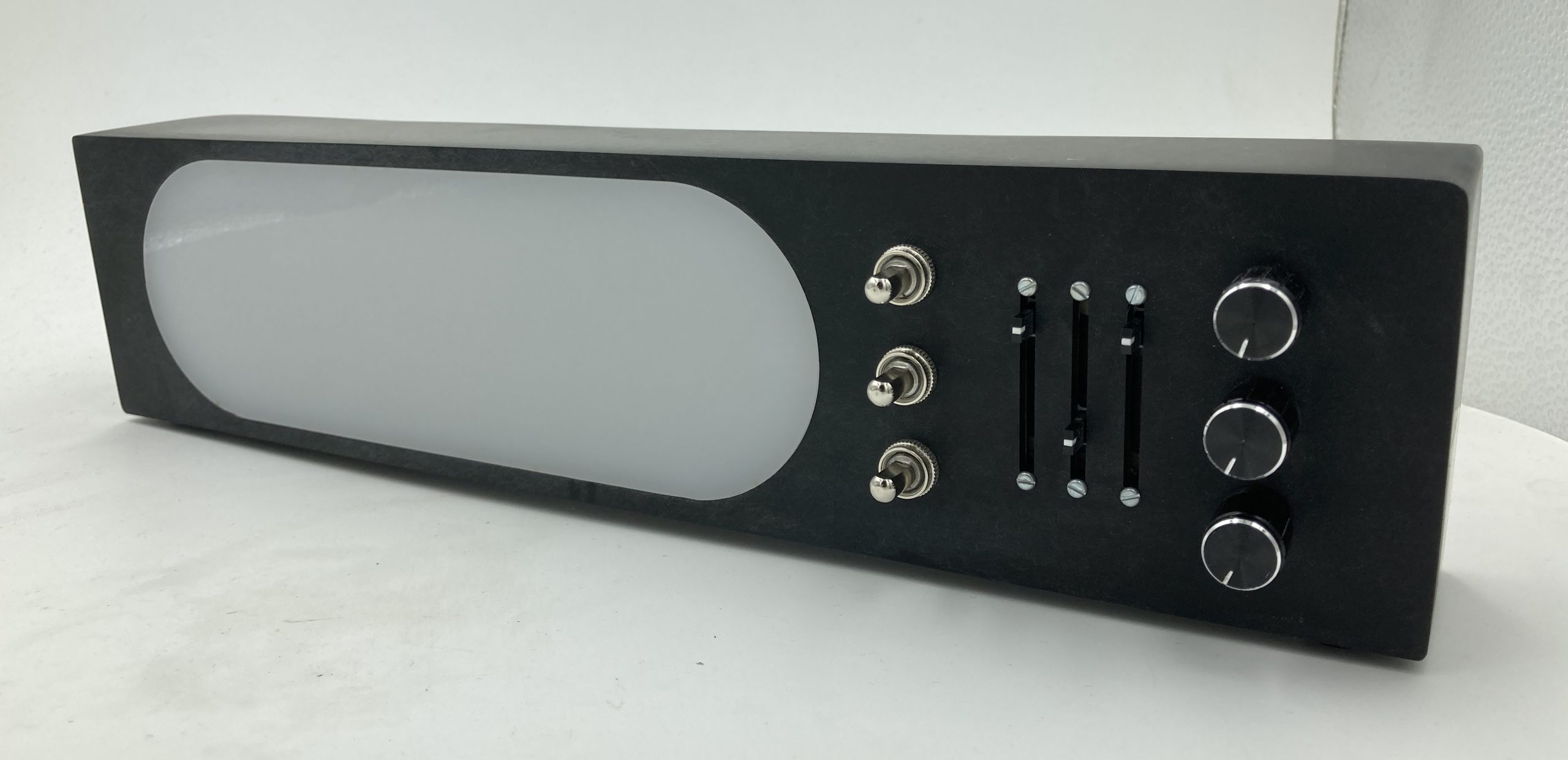
A matte black acrylic housing contains LED strip lights whose luminance is diffused by an oblong, semi-opaque, white face in the front of the box. With the power of a 5V cord and plug, an on/off switch in the back turns the LEDs on. On the front there are 3 of each component: push buttons, sliders, and dials. Each RGB color (red, green, and blue) in the LEDs is controlled by one of each component. The buttons turn the lights on and off, the sliders change their brightness, and the dials change their brightness as well. With fine tuning, the user can explore a wide range of colors.
Process Images
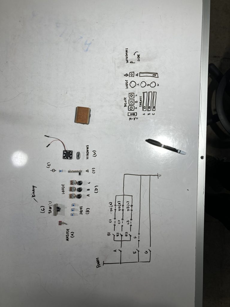
Figuring out the basics of the interactions I planned to use in my project. An array of sliders, knobs and buttons make the object more engaging.
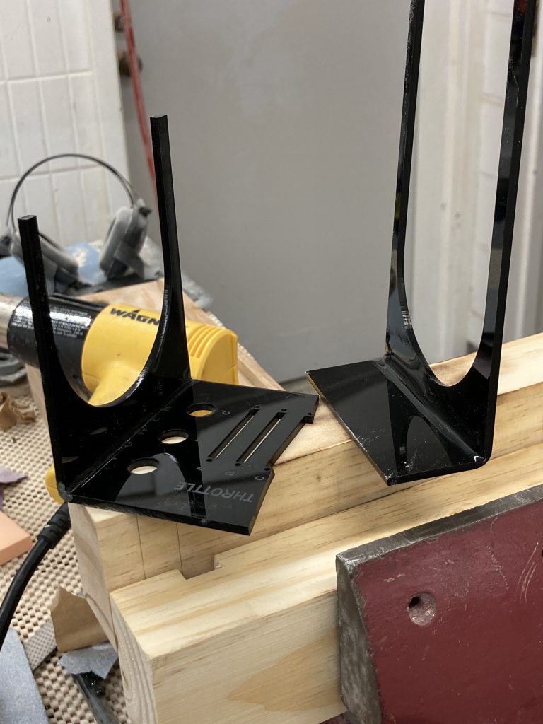
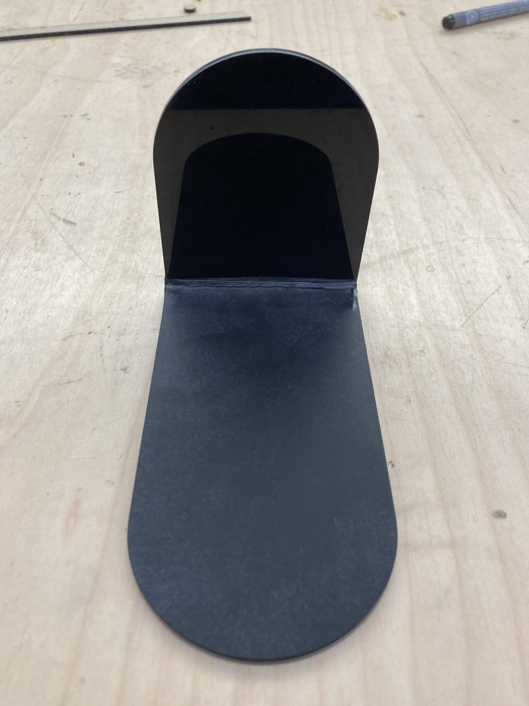
I decided that bent corners, although more difficult to achieve, would be more elegant than just 6 sides of a rectangular prism glued together. These were my experimentation and practice bends using extra acrylic from failed cuts. The yellow heat gun in the back is what I used to make the rigid acrylic more malleable.
Upon realizing how fingerprint-prone glossy acrylic was, I experimented with a circular sander. I tried a couple of different grits to see what would create the cleanest matte finish. P180 was the winner. Here is a piece whose top part is untouched, and whose bottom half is sanded with P180.
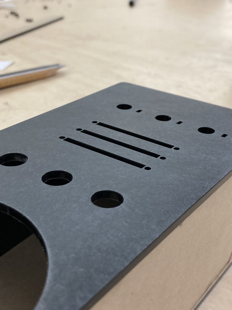
A fully sanded bare bones version of the front piece with all the holes measured out and oriented to neatly fit the components.
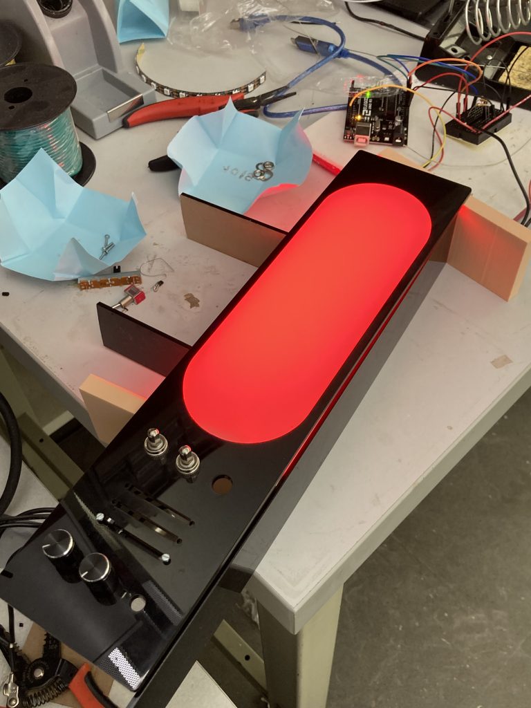
The first light! Propped up on foam blocks, I tried to simulate what the object would look like fully assembled. This was the first time I was able to see what the LED lights would look like through the semi-opaque diffusing acrylic.
Process Reflection
For me, this project was a success. Although my concept was heavily informed by my major (product design), I definitely learned a number of new things. First the capabilities of Arduino; this was my first ever experience using an Arduino, so it was interesting to see what could be done with it and how it’s integrated into a programmed object. Secondly, it was enlightening to brush up on my wiring ability. I’ve only ever programmed and wired anything once before, and it was a much simpler mechanism. Using a breadboard was helpful, but it was a good reminder of the arduous process of soldering and wire management. Also, the breadboard: I struggled for a number of hours over the breadboard, and completely scrapped even more hours of work with the intention of just doing the wiring directly. But, for some reason after doing that, something went off in my head and I immediately grasped how the breadboard worked, and I rewired everything in a matter of minutes. It made the wire management a lot easier and circumvented a lot of soldering that would have made my assembly process a lot slower.
I think that my project gave the user a very different experience than the other students’ projects did, but not in a better or worse way. I think that with my design background, I was able to take a simple form, as well as a simple interaction, and make it engaging and elegant with careful visual and interactive decisions. If I were to do this project again with the knowledge and experience that I have now, I think I would do a bit more iteration on the form. I would also try to add an additional interaction, that would control a black strip light that would add an interesting element to the LEDs. It would be cool to see how the two types of lights interaction in one visual field. This project having been my first time working with acrylic in the way that I did, I would come up with a better way to execute that process more cleanly there were flaws that I was able to buff out, but that created problems during final assembly. I also would have taken more time to do calculations before assembly, just to achieve tighter fitting parts. Overall, though, I think my craft was decent. Considering that all of the craft processes were relatively new to me, I think I did well in that field, and learned a lot about DFA (designing for assembly) and DFM (designing for manufacturing) approaches. I would love to explore and iterate on this more, and try to develop a process that could be translated to a mass production scale, just for the purpose of understanding how a product like this would perform in the real commercial world.
Detail Images
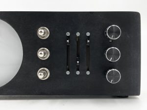
Interactive Components Close-Up
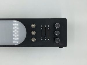
Control Pad
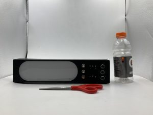
Scale Reference. Main Housing Dimensions: 14.75″ L x 3.5″ W x 2.25″ D
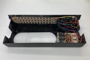
Opened up view of interior components. The housing being openable and closable was important for the sake of maintenance.
Interaction Video
Link: https://drive.google.com/file/d/1wL3T_zTrbQyLEtgYcx1JT8Xm8iEySVQE/view?usp=share_link