Course Kit Guide
The course includes a kit of electronic parts which will enable a wide array of small projects. Students are responsible for their own mechanical or structural materials, project housings, or decorative elements. The following is a quick visual guide to everything provided in the kit. For reference, the total cost is about $35 per kit in bulk.
Inventory
| Description | Kit Quantity | Approximate Price Each |
|---|---|---|
| Newspring 24oz takeout container with lid | 1 | $1.00 |
| Arduino-Compatible Uno R3 EDArduino incl. USB cable | 1 | $7.20 |
| 9G Micro-Servo (For RC Helicopter Boat Plane Car) | 1 | $3.10 |
| IRF540 MOSFETs | 2 | $0.85 |
| Solderless Breadboard, Long | 1 | $4.00 |
| ADXL345 Triple-Axis Accelerometer Module | 1 | $2.30 |
| General Wire Kit (Approx 65pcs) | 1 | $2.10 |
| assorted 5mm colored LEDs | 20 | $0.10 |
| HC-SR04 Ultrasonic Proximity Sensor | 1 | $1.30 |
| Mini Speaker, 0.5W, 8Ohm | 2 | $0.60 |
| Photointerrupter, through-beam, V69 605 TCST 1103 | 1 | $1.05 |
| Photointerrupter, reflective, NPN Phototransistor, LTH 1550-01 | 2 | $0.35 |
| 7805 regulator, TO-220 | 1 | $0.50 |
| 1N4004 diode | 2 | $0.10 |
| ULN2003A Darlington Driver, Transceiver, DIP16 | 2 | $0.20 |
| SPST momentary switches | 5 | $0.05 |
| SPST lever microswitch | 2 | $1.10 |
| DPDT slide switches | 2 | $0.05 |
| 10K board-mount potentiometers | 2 | $0.20 |
| pager motor | 1 | $1.95 |
| 5mm Mini Photocell, CdS photoresistor | 2 | $0.05 |
| resistor, 1/4W, 10K | 10 | $0.01 |
| resistor, 1/4W, 220 ohm | 10 | $0.01 |
| resistor, 1/4W, 100 ohm | 10 | $0.01 |
| resistor, 1/4W, 5.6K | 10 | $0.01 |
Core Components
Arduino
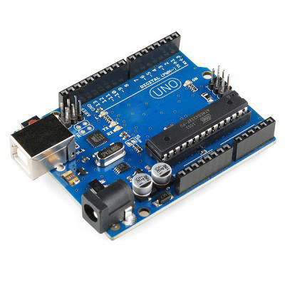
The Arduino is the tiny computer (microcontroller) we will programming in this course. It also comes with a blue USB cable (not shown) to plug into a laptop in order to program it. It’s easiest to power through the USB cable, but it can also get power from another source that provides 7–20V DC.
Solderless Breadboard
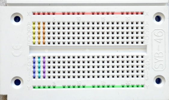
A breadboard is a time-saving device that lets you connect things electronically.
The internal connections are hidden and they follow a convention that can be surprising at first:
In any row, a,b,c,d,e are connected to each other.
Likewise, in any row, f,g,h,i,j are connected.
- Along each edge there’s a long blue and red stripe:
- The whole red column is connected.
- The whole blue column is connected.
Jumper Wires
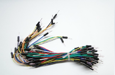
The jumper wire kit is used to build circuits. The wires can plug either into the Arduino connectors or the breadboard circuit points.
The kit we provide has wires with “pins” at both ends, and therefore these are called “male-male” wires. Wires can also terminate in a receptacle, which is called a “female” end, so a wire with receptacles at both ends is a “female-female” wire. The third type, of course, is the “male-female” wire, which acts like an extension cord.
Plastic Box
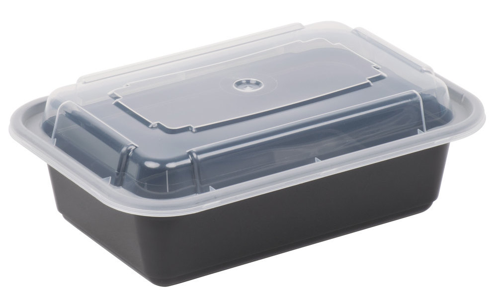
It’s a 24 oz takeout container to hold everything else, but could also be used as a housing for a project.
5.6K Resistors
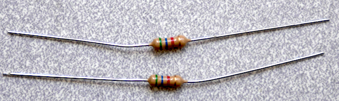
These are 5.6K (5,600 Ohm) resistors we will use as ‘pull-up’ resistors for switches and photosensors. The green-blue-red-gold color bands indicate the value using the standard resistor code code. Green-blue indicates ‘56’, and red adds two zeros for ‘5,600’ ohms.
The gold band indicates a +/- 5% manufacturing tolerance around the nominal value, meaning the highest value this one should be is 5,600 Ohms x 1.05 = 5,880 Ohms, and the lowest it should be is 5,600 Ohms x 0.95 = 5,320 Ohms. (If you spend more money, you can get resistors with tighter tolerances but for general applications it’s not necessary.)
The kit resistors are rated at 1/4 Watt dissipation. If you push more than 0.25 Watts of power through them, they are at risk of overheating.
270 Ohm Resistors
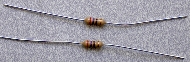

These are 270 Ohm resistors we will use as ‘dropping’ resistors for LEDs. The red-violet-brown-gold color bands indicate the value using the standard resistor code code. Red-violet indicates ‘27’, and brown adds one zero for ‘270’ ohms. The gold band indicates a +/- 5% tolerance on this value. These are carbon-composition resistors rated at 1/4 Watt dissipation.
Sensing (Input)
Switches
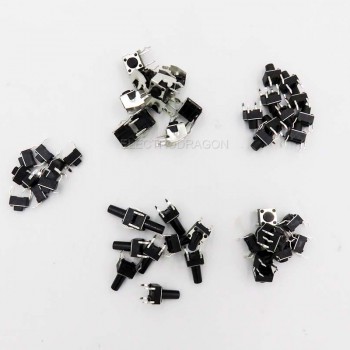
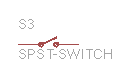
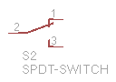
Several small switches are provided. This usually need to be connected in a simple circuit with a resistor to produce a change in electrical voltage or current from a mechanical input.
Photoresistor
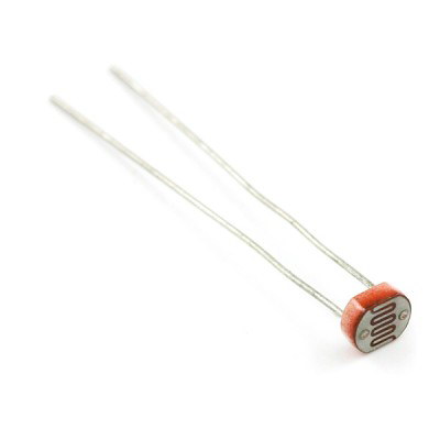

The photoresistor is a simple optical transducer which changes resistance in response to overall light level.
HC-SR04 Ultrasonic Ranger
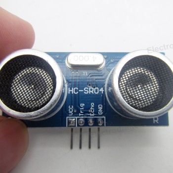
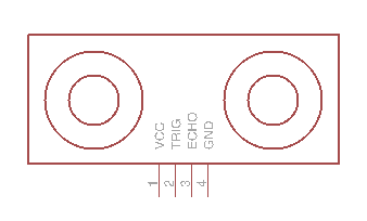
The ultrasonic ranger is a single-channel sonar which emits short pulses of ultrasonic sound and times the interval until an echo is detected. They can be used for detecting proximity and measuring distance.
Accelerometer Module
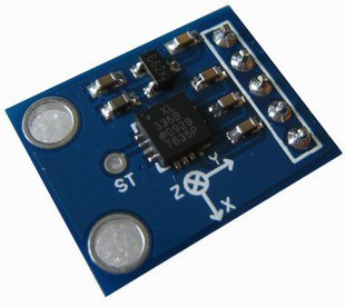
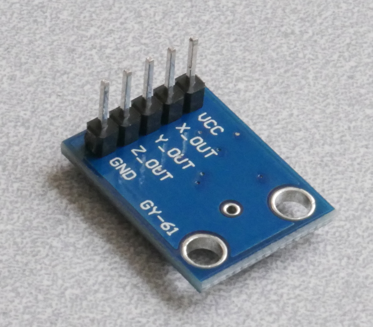
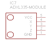
The 3-axis ADXL335 accelerometer is an inertial sensor which measures either tilt or acceleration. This module also includes a voltage regulator to reduce a 3-5V supply to a safe supply voltage for the sensor.
The sensor chip on the module is an ADXL335: home page, datasheet.
Note: the pins are included unassembled in the package and must be soldered to the board.
Actuation (Output)
LEDs
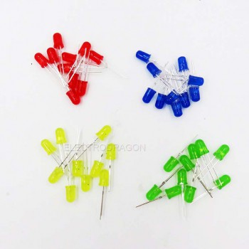

Several LEDs are provided. This must be used with an appropriate resistor to limit the total current.
Micro Servo
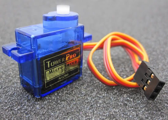
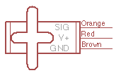
The micro servo is a motor with position control. The Arduino can generate a particular control signal indicating the angular position to which the servo should rotate. Internally it has a gearmotor, position sensor, and feedback circuit to reach and hold a target angle.
Transistor Driver Integrated Circuit
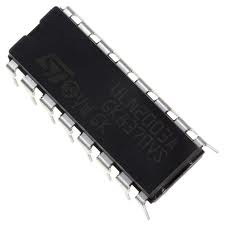
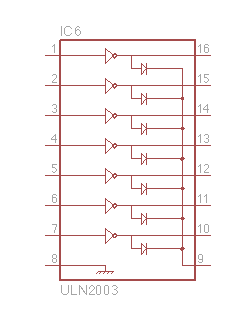
The ULN2003 is an integrated circuit with seven output channels capable of driving a motor, speaker or solenoid at higher power levels than the Arduino can itself provide.
Speaker


The speaker (half-Watt, 8-ohm) can be driven with the ULN2003 to make tones. Wires will need to be soldered to the pads in order to connect to the breadboard.