2.4.18. Exercise: DRV8833 Dual DC Motor Driver
2.4.18.1. Objective
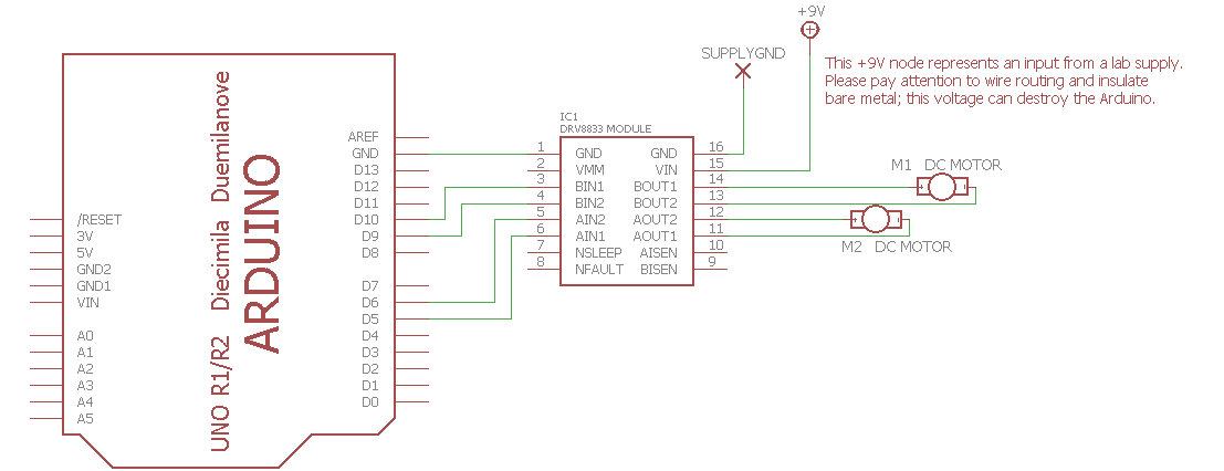
Control a pair of DC motors using a driver module.
Driving a DC motor in either direction requires a circuit which can control the direction of the current. A common solution is to use a H bridge circuit topology which uses four switches operated in pairs to drive the supply current either forward or backward through the motor winding. The circuit is commonly drawn like the letter H with a motor on the crossbar and a switch on each leg. The bridge could be implemented using mechanical switches or relays, but for fast control with PWM it is common to use solid-state switches such as MOSFET transistors.
This exercise uses a module incorporating a DRV8833 driver chip which includes two H bridges and can drive two small DC motors bidirectionally. Speed control is supported by generating PWM signals in an Arduino to vary the average motor current. The bridges can also be wired in parallel to drive a single motor with twice the current.
2.4.18.2. Steps and observations
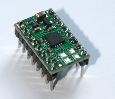
Find a DRV8833 module in the lab. The part comes without connectors installed, so if you find a new part you will need to solder two eight-pin header rows on the board so it can be used on a breadboard. Be sure to solder every pin. The recommended orientation is as pictured, with the driver chip on top, since the pin layout then matches the schematic symbol. You may find parts in the drawer with the pins soldered on the opposite side (silkscreen up, chip down); that orientation works fine, but please pay attention to the signal labels on the silkscreen so you make correct connections since the pin positions will be mirrored from the schematic symbol.
Load and run the WheelDrive sketch.
Observe the DC motor motion and compare against the code.
Try writing a ramp function to produce smoother speed changes. Can you choreograph a smooth motion sequence?
2.4.18.3. Comments
PWM can create a varying motor current and the motor speed will change, but does not regulate the speed; precision speed control requires measuring the speed with a sensor and applying closed-loop feedback to compensate for friction and other loads.
The H Bridge has four basic modes: forward, backward, coast, and brake. Forward and backward currents are created by turning on either diagonal pair of switches. Coasting occurs when all switches are off. The motor is braked when either only the top pair or bottom pair are turned on. The braking occurs because a spinning DC motor also acts as a generator; if the winding is left open, it will develop a voltage. However, if the winding is shorted, a current will flow which is dissipated as heat in the winding. This creates a damping effect which slows the motor. The sample code only uses the coasting mode but could be changed to use a braked mode by driving both control lines HIGH to stop instead of driving both LOW.
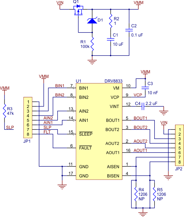
The schematic for the DRV8833 module shows that the driver module is mostly a breakout board for the surface-mount driver chip, but includes reverse-supply protection, pullup resistors, pulldown resistors, charge-pump capacitors, and decoupling capacitors which filter the power. The board has the capability of adding current-sensing resistors, but does not by default limit current.
2.4.18.4. Arduino Code
- Documentation: WheelDrive Arduino Sketch
- Sketch Folder: WheelDrive
2.4.18.5. Other Files
- EAGLE file:
DRV8833-motor-driver.sch