2.4.5. Exercise: Continuity Tests
2.4.5.1. Objective
Learn typical scale of resistance units.
Metals are generally good at conducting electricity; they have low resistance. Common insulators (including air) have a resistance high enough it can’t be easily measured. So the most basic resistance measurement is the ‘continuity check’ which simply tests whether the resistance is low enough to be considered a conductor, or whether it is unexpectedly high representing an open circuit.
2.4.5.2. Steps and observations
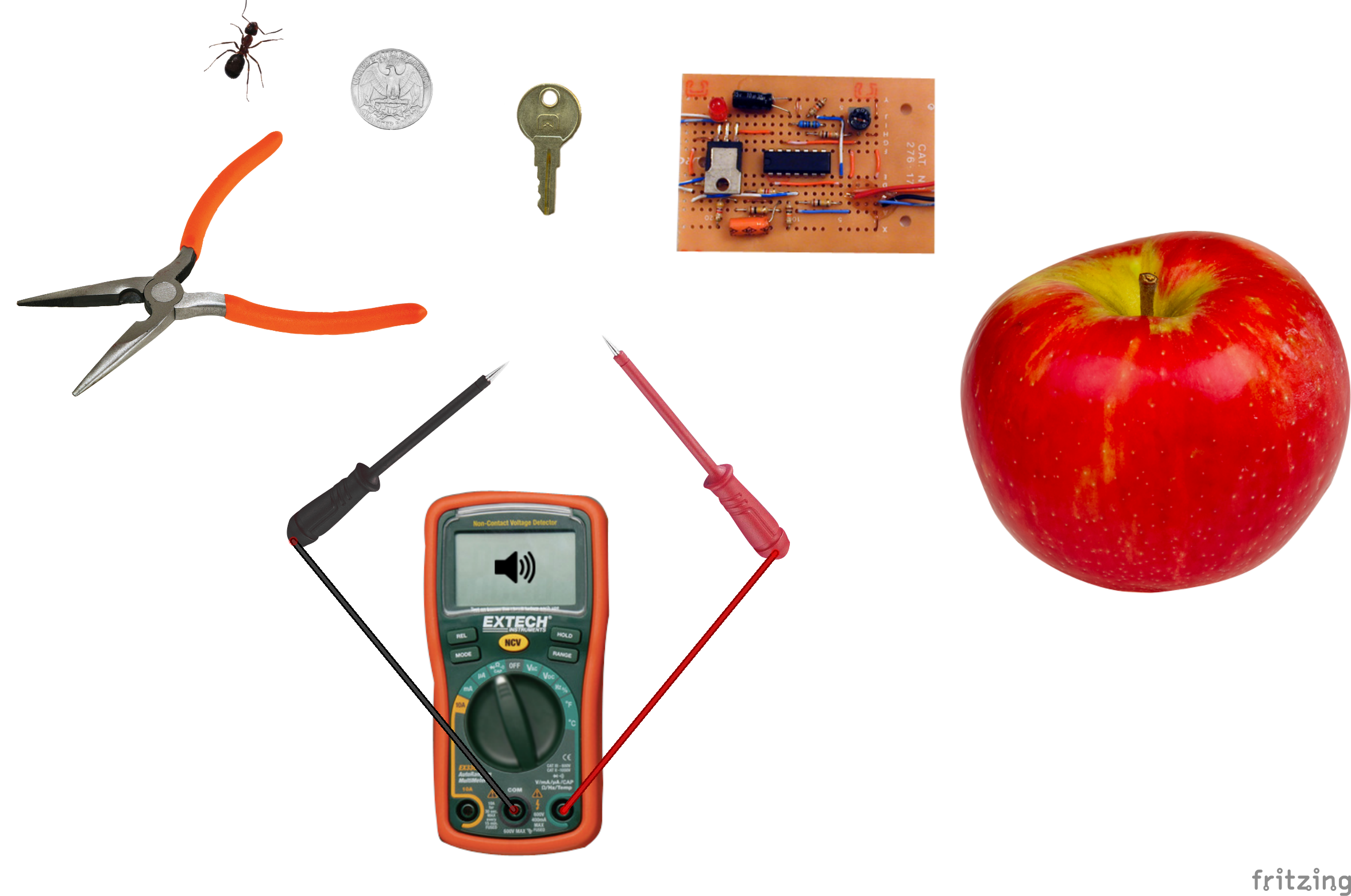
- Set the DMM to resistance: Ohms, or the large greek omega letter Ω. The DMM will emit a small voltage to measure the current which flows in response through the resistance path between the probes.
- Hold the probe tips in your fingers. This is safe, the DMM voltage emitted is very low. Squeeze harder. Moisten the contact point. You should see a body resistance reading which changes with conditions.
- Touch the probes to a coin, keys, and metal tool surfaces. If you fail to see a low reading, try changing contact points, scratching the surface, and pressing harder.
- Touch the probes across the leads of a resistor. The quarter-watt resistors with wire leads we use in the lab have colored bands which encode the specified value.
- Touch the probes across the leads of an LED. Reverse the connections.
- Try measuring resistance through other natural objects, food, furniture, etc. Write down your results.
2.4.5.3. Comments
Typical resistance measurements along a short wire will be less than 1 ohm and are often dominated by the resistance of the contact point and probe wires. Component resistors are available in standard ranges from a fraction of an ohm to tens of millions of ohms. For our typical sensor circuits we will be using resistors in the 100 to 10000 (10K) ohm range.
2.4.5.4. Other Files
- Fritzing file:
continuity-tests.fzz