Pinball Arduino Mega Shield
Pinball games involve many individual sensors and actuators connected to the logic with a lot of wiring. This is a vulnerable point for building a machine which is engaged physically by the player. In an effort to simplify the wiring problem, the course provides a ‘shield’ board which interfaces the Arduino microcontroller to a useful set of interface hardware and connectors for driving the physical game.
For 2019 we have a new larger shield which fits an Arduino Mega and provides more I/O. It is an expansion of the previous Pinball Arduino Uno Shield which fit onto a single Arduino UNO.
Contents
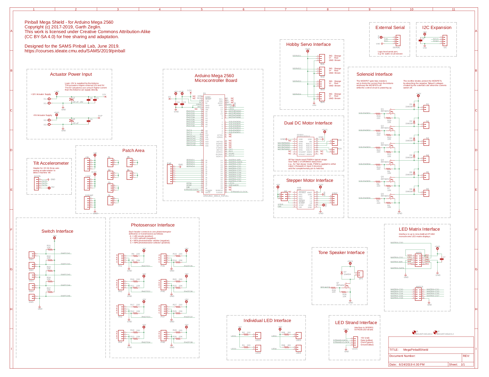
Pin Assignment Notes
The Arduino Mega 2560 has considerably more I/O pins than an Arduino UNO, so there is less contention overall for special functions.
- The Serial port lines TX0 and RX0 are used for communication with the USB port and so are still unavailable for PWM output.
- The available PWM lines are D2 through D13, D44, D45, and D46 (15 total). Ten of these will definitely be PWM: six solenoids and four H-bridge controls. The remaining five are used for the four external LEDs and the tone speaker, which may or may not benefit from PWM.
- Sixteen ADC inputs are available. Eight are connected to photosensor inputs, three to the tilt accelerometer, and five to switch inputs. This would allow the switch inputs to be repurposed for general analog sensing.
- The LED matrix uses 11 GPIO lines for clock, data, and nine chip selectss
- The WS2801 LED strand uses hardware SPI on D51 (MOSI) and and D52 (SCK). D50 (MISO) and D53 (CS) are left unconnected to allow alternate SPI uses.
- Serial port 1 is connected to a header to use for a co-processor, e.g. an external serial-controlled MP3 player module for audio output. Serial ports 2 and 3 are left unconnected (e.g. available). The labels are relative to the Arduino: TX1 is an output from the Mega, RX1 is an input to the Mega.
- The seven odd numbered GPIO pins D31, D33, etc. through D43 are pinned to an expansion header.
- The remaining GPIO pins are left disconnected.
External Resources
Product information:
- DRV8833 Dual Motor Driver Carrier
- A4988 Stepper Motor Driver Carrier
- 16x24 Red LED Matrix Panel - Chainable HT1632C Driver, 16x24 LED Matrix Tutorial
Library documentation:
Related course exercises, with sample circuits, code, and explanation:
- https://courses.ideate.cmu.edu/16-223/f2018/text/ex/Arduino/digital-read-serial/digital-read-serial.html
- https://courses.ideate.cmu.edu/16-223/f2018/text/ex/Arduino/servo-sweep/servo-sweep.html
- https://courses.ideate.cmu.edu/16-223/f2018/text/ex/Arduino/unipolar-drivers/unipolar-drivers.html
- https://courses.ideate.cmu.edu/16-223/f2018/text/ex/Arduino/DRV8833-motor-driver/DRV8833-motor-driver.html
- https://courses.ideate.cmu.edu/16-223/f2018/text/ex/Arduino/stepper-motor/stepper-motor.html
- https://courses.ideate.cmu.edu/16-223/f2018/text/ex/Arduino/read-analog-accel/read-analog-accel.html
- https://courses.ideate.cmu.edu/16-223/f2018/text/ex/Arduino/WS2801-LED-SPI/WS2801-LED-SPI.html
Adafruit 16x24 LED Matrix Display Notes
The tutorial explains how to chain multiple modules together. Each module shares clock and data, but needs its own chip select. The following notes might help clarify the meaning of the names of each pin and the actual internal wiring.
The back of each module has four 10-pin male headers intended for daisy-chaining the modules from left to right (as viewed from the back of the board). With only two modules, only the upper pair of headers are required. With three or more modules, all four headers are needed.
The internal connections are as follows. The upper-left header has CS0 connected to the left half of J5 and CS1 connected across to the CS0 position on upper-right header. The right half of J5 is the actual chip select (CS). So with J5 in place, upper-left CS0 feeds CS on the first module, then upper-left CS1 becomes ‘CS0’ and CS on the second module (with J5 also bridged). The CS1 position on the upper-right header does not appear to be connected.
The lower-left header has the CS0 position directly connected to CS. The lower-left CS1 connects across to the CS0 position on the lower right, as with the others up to CS8 connecting across to CS7 on the right. The lower-right CS8 appears disconnected.
So it appears that it should be possible to actually chain eleven modules, since there are actually a total of eleven chip select inputs between the two headers. The first two modules would have J5 installed and use the upper-left CS0 and CS1. With the third and beyond, J5 would not be installed, and the lower daisy-chain begins, with the first lower-left ‘CS0’ signal used as chip select on the third module.
However, in the interests of keeping the modules identical, this design duplicates CS0 and CS1 on the lower header. This allows the two-module usage to use the single daisy-chain (with J5 installed on both), and longer chains to use a double daisy-chain and ignore the upper CS0 and CS1 (with J5 installed nowhere). The longest possible chain is then nine modules.
Licensing

The MegaPinballShield design and documentation by Garth Zeglin are licensed under a Creative Commons Attribution-ShareAlike 4.0 International License. Based on a work at https://courses.ideate.cmu.edu/SAMS/2019/pinball.