Day One
|
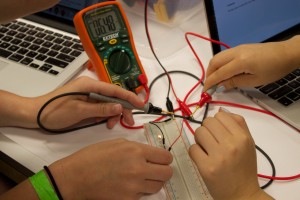
Thanks everybody, for helping this class get off to a great start. The energy and enthusiasm is palpable. I noticed a few recurring technical questions which we can address. The power supplies have current limit settings which govern the maximum current it will output from each channel. If the draw is too high (e.g. load resistance too low), it will drop the voltage to meet this limit. Some power supplies had this knob set at zero and were properly refusing to output any current. The power supplies have series, parallel, and independent modes: we will almost always use independent mode. The other two modes gang the two halves together: series can offer higher voltages, parallel can offer high currents. If in doubt, check the manual. The DMMs have a diode measurement mode for measuring the forward voltage drop, but it doesn’t work for the purple LEDs, most likely because the forward voltage drop is too high because of the particular chemistry, which is also related to the color. The lab meters don’t even work for the red LEDs, although they will measure the 0.6 volt drop of a 1N914 diode. I used a better meter (a Fluke 179) to test one of our red LEDs and it showed a voltage drop of 1.79V. However, even the better meter was only able to light the purple LED but not register its voltage drop. Not all of the DMMs had the probes with the long tips; the long tips make the AC wall measurement much easier. I answered a few other miscellaneous questions about the following: resistor color code, breadboard layout, switch pin layout (e.g. DPDT pinout), and meter usage. If any of this is confusing, please keep investigating, asking each other, asking the instructors, it will all become clear. Several people were surprised by the fact that the resistance of the bulb was different when hot. Brief reminders:
|

