Final Project – RF Sensor
|
Rf Signals
Team: Sara Johnson as designer, integrator, and tutor Annabelle Lee as scribe, designer, and integrator
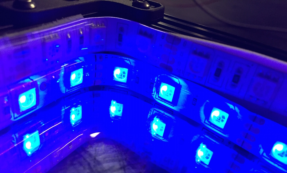
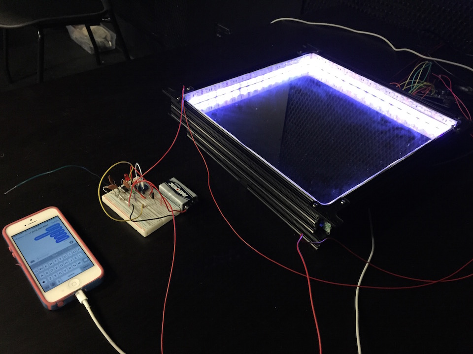
Introduction: There are thousands of invisible cell phone signals bouncing around us. Our team set out to visualize and experience the invisible data flying through the air that that consume our attention. We narrowed our focus on rf signal emitted by cellphones, and created a light display that fades and flickers in response to the background noise created by our constant use of cellphones, and dramatically flashes and changes color when a phone sends or receives data nearby.
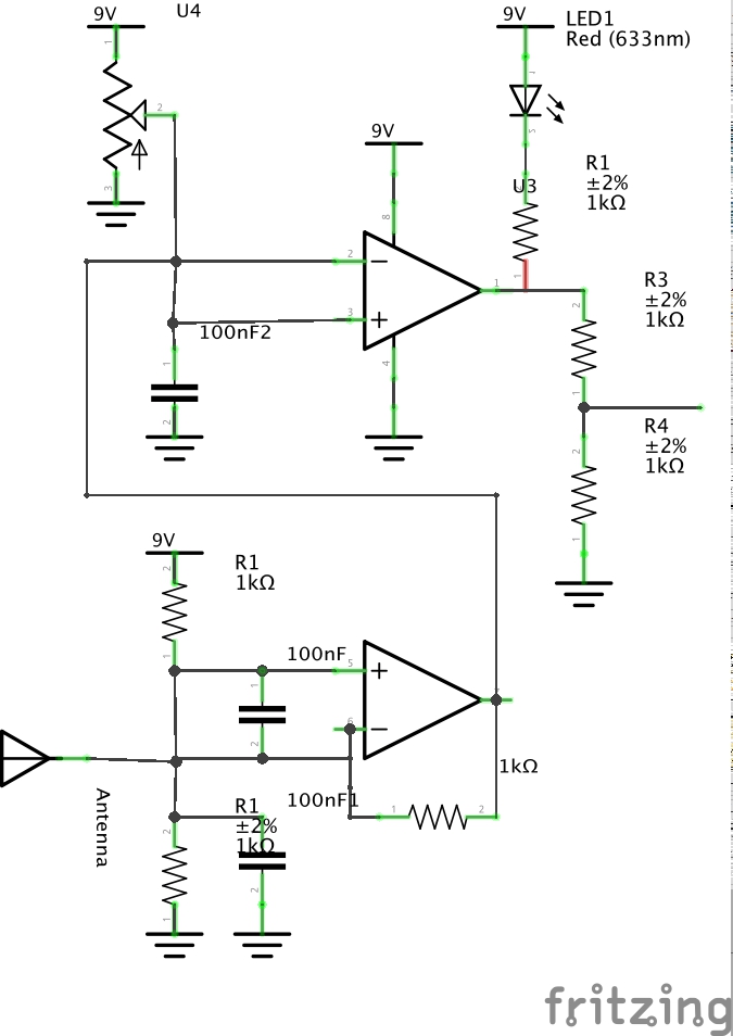
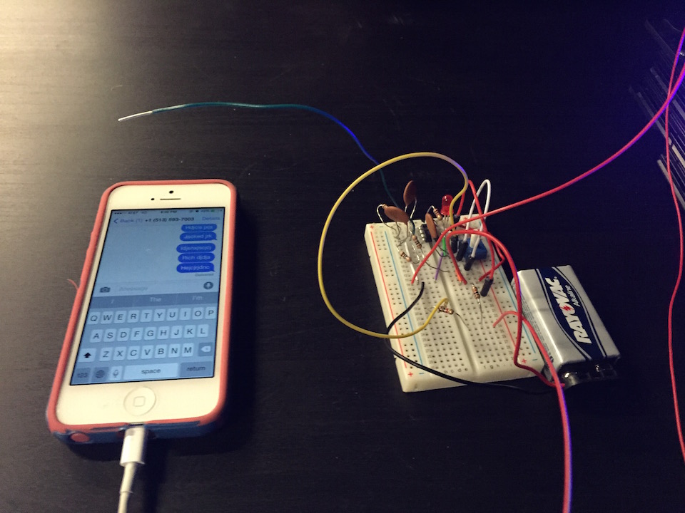
Technical Specs: We used a 16 cm antenna to sense rf signals emitted from phones, emitting signals at a frequency of about 1800 MHz standard GSM (Global System for Mobile Communications). 1 cm of the antenna wire was stripped and exposed to collect signal. It can detect any cell phone activity such as incoming or outgoing calls, texting, and data usage. The sensitivity is adjusted with a potentiometer.
The sensed signal is amplified through an op-amp, and the sensitivity is adjusted with a potentiometer to a level of sensitivity to ignore background noise and react to large packets of data. THe signal is analyzed through the signal the Arduino’s analog input and determines the frequency using arduino timer interrupts.
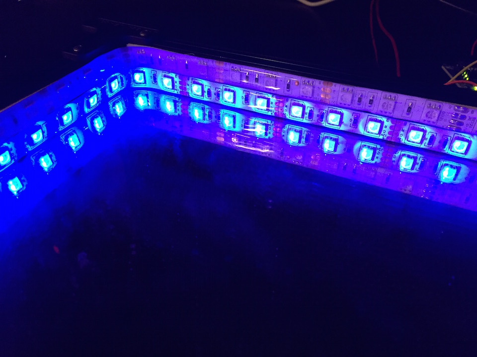
The two analog LED strips are powered by 12V and setup with 6 N-powered mosfets, one mosfet for each color.
Circuit Schematic:
http://www.jerome-bernard.com/blog/2013/01/12/rgb-led-strip-controlled-by-an-arduino/
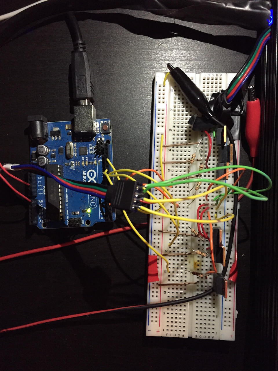
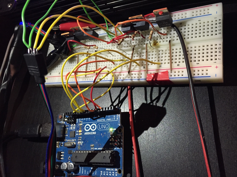
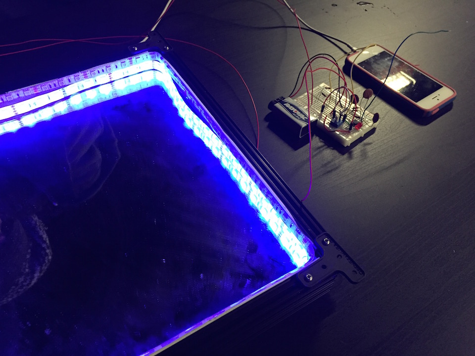
Pictures:
Arduino Code: The below code uses Amanda Ghassaei’s “sine wave freq detection with 38.5kHz sampling rate and interrupts” code available here: http://www.instructables.com/id/Arduino-Frequency-Detection/
//clipping indicator variables boolean clipping = 0;
//data storage variables byte newData = 0; byte prevData = 0;
//freq variables unsigned int timer = 0;//counts period of wave unsigned int period; int frequency;
void setup(){
Serial.begin(9600);
pinMode(13,OUTPUT);//led indicator pin
cli();//diable interrupts
//set up continuous sampling of analog pin 0
//clear ADCSRA and ADCSRB registers ADCSRA = 0; ADCSRB = 0;
ADMUX |= (1 << REFS0); //set reference voltage ADMUX |= (1 << ADLAR); //left align the ADC value- so we can read highest 8 bits from ADCH register only
ADCSRA |= (1 << ADPS2) | (1 << ADPS0); //set ADC clock with 32 prescaler- 16mHz/32=500kHz ADCSRA |= (1 << ADATE); //enabble auto trigger ADCSRA |= (1 << ADIE); //enable interrupts when measurement complete ADCSRA |= (1 << ADEN); //enable ADC ADCSRA |= (1 << ADSC); //start ADC measurements
sei();//enable interrupts }
ISR(ADC_vect) {//when new ADC value ready
prevData = newData;//store previous value newData = ADCH;//get value from A0 if (prevData < 127 && newData >=127){//if increasing and crossing midpoint period = timer;//get period timer = 0;//reset timer }
if (newData == 0 || newData == 1023){//if clipping PORTB |= B00100000;//set pin 13 high- turn on clipping indicator led clipping = 1;//currently clipping }
timer++;//increment timer at rate of 38.5kHz }
void loop(){ if (clipping){//if currently clipping PORTB &= B11011111;//turn off clippng indicator led clipping = 0; }
frequency = 38462/period;//timer rate/period //print results Serial.print(frequency); Serial.println(” hz”);
delay(100); }
Antenna: You can switch out antenna lengths according to which frequency of signals you’re looking to capture. Our antenna is 16cm. 2.4 GHz = 12.5 cm / Bluetooth, WLAN 1800MHz = 16 cm / E Netz GSM 900MHz = 33 cm / D Netz GSM 500 MHz = 60 cm / DVBT K24 Television 100 MHz = 150 cm / FM Broadcast
Or, you can calculate using the below equation. λ=c/f = (300.000km/h)/900MHz =33.3 cm Then; Antenna Length = λ / 2 = 16.6 cm
|