2.1.22. Exercise: Event-Loop Programming
2.1.22.1. Objective
Create several simultaneous signals to explore program event scheduling.
The world is intrinsically a parallel, simultaneous place, but computers are serial, sequential devices. Even modern multi-core machines are still constructed around many small execution units rapidly performing many tiny computations in sequence. So bridging the gap between information in the physical world and as represented in a computation ultimately requires creating the illusion of simultaneity through careful attention to time within a program.
The essence of multiprocessing is rapidly alternating between multiple tasks through some form of time-slicing. Operating systems perform this at the level of applications or threads, but on a tiny computer such as the Arduino we can do essentially the same at the level of individual I/O operations. So rather than initiating an I/O operation and waiting for it to finish, the time is recorded for when to next check the operation, and the program continues checking whether some other action is ready. This sequential testing for readiness is called polling, and this iteration is one form of an event loop or event-driven programming.
This process also highlights that all digitized signals are sampled in time. It is useful if those samples are also periodic at a fixed rate, since that is what allows predictable filtering such as smoothing and boundary detection.
The simplest form of polling is a synchronous system in which all computations run within a single fixed time cycle. However, in this example the input and output can run at very different rates, since each output must change at a different audio rate and the input changes at a much slower human control rate. So this example uses a form of asynchronous polling.
The basic structure of our event loop will be built around a set of timers which are polled as fast as possible. Each timer is simply a timestamp with associated interval:
long next_output_time_1 = 0;        // timestamp in microseconds for when next to update output 1
long next_output_time_2 = 0;        // timestamp in microseconds for when next to update output 2

long output_interval_1 = 500;       // interval in microseconds between output 1 updates
long output_interval_2 = 700;       // interval in microseconds between output 2 updates

int output_state_1 = LOW;           // current state of output 1
int output_state_2 = LOW;           // current state of output 2

void loop()
{
  // read the current time in microseconds
  long now = micros();

  // Polled task 1 for output 1.  Check if the next_output_time_1 timestamp has
  // been reached; if so then update the output 1 state.
  if (now > next_output_time_1) {

    // reset the timer for the next polling point
    next_output_time_1 = now + output_interval_1;

    // toggle the output_state_1 variable
    output_state_1 = !output_state_1;

    // update output pin 1 with the new value
    digitalWrite( outputPin1, output_state_1 );
  }

  // Polled task 2 for output 2.  Check if the next_output_time_2 timestamp has
  // been reached; if so then update the output 2 state.
  if (now > next_output_time_2) {

    // reset the timer for the next polling point
    next_output_time_2 = now + output_interval_2;

    // toggle the output_state_2 variable
    output_state_2 = !output_state_2;

    // update output pin 2 with the new value
    digitalWrite( outputPin2, output_state_2 );
  }
}
The key idea of this program can be illustrated in the following diagram:
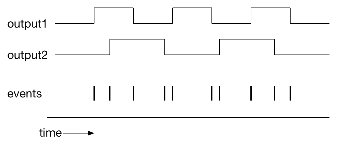
Even though the output signals are continuous in time, they can be treated as a series of discrete events at the transition points. The logic of the timestamp allows the whole program to consider the net activity as a single series of individual events, even as the program is structured around individual outputs.
2.1.22.2. Steps and observations
- Load and run the EventLoopDemo sketch. The example program generates audio-frequency square waves at different pitches on pins 4 and 5 to demonstrate a simple event-loop control structure allowing parallel execution of two timed tasks. In a later step you will read an analog potentiometer input and use the input value to modulate the pitch by varying the waveform timing.
- Observe the initial outputs on an oscilloscope and measure the period of the waveforms.
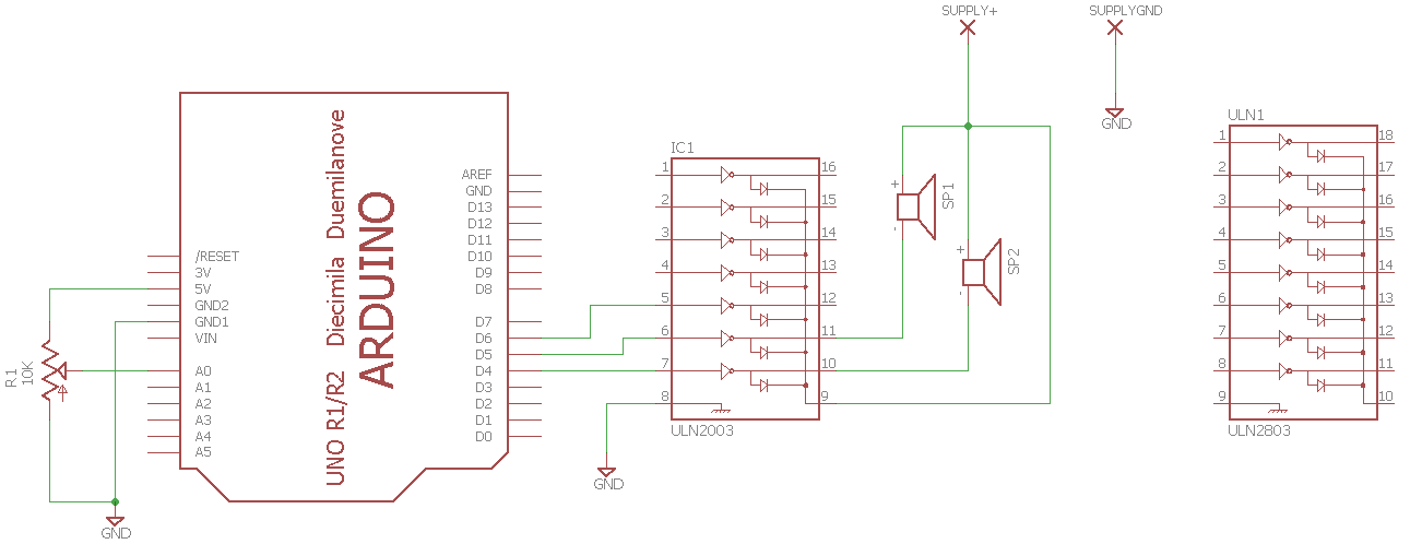
- Construct an Arduino circuit incorporating a potentiometer for analog input and two audio speakers for digital output. A reference schematic is shown below which uses a ULN2003 or ULN2803. A small speaker is typically about 8 ohms and can handle a fraction of a Watt; assuming 1/8 Watt, the power supply voltage would be typically be about a volt above the ULN2803 forward drop, so start with a power supply voltage of 1.6V and experiment.
- Add an additional timed task to read the potentiometer at a slower rate.
- Add a simple linear mapping to update the output frequencies based on the potentiometer input value, i.e., map the analog input to the output intervals.
2.1.22.3. Sample Circuit
Please use a lab supply for the speaker supply so the voltage can be easily varied for testing. Please be sure to set it to a low voltage (less than 3V) before connecting it. The test circuit is very similar to Exercise: Multichannel Bipolar Transistor Driver.
2.1.22.4. Comments
The event loop example as shown is subject to variation in the sample rate termed jitter since each time stamp is computed from the current time rather than the previous time stamp. So variation in the execution time of each polling loop can create variation in the overall sampling rate. This can be fixed by computing new time stamps from the previous time stamps, but care must be taken to handle initialization correctly, e.g., checking whether the current time is very different from the time stamps.
Experienced programmers will also recognize the possibility of creating a data object type representing a timed task, either as a C structure or a C++ class. This would reduce the repetition in the code.
2.1.22.5. Arduino Code
- Documentation EventLoopDemo Arduino Sketch
- Sketch Folder: EventLoopDemo