7.24. Practicum-2016 Arduino Sketch
This is the reference solution for the 2016 16-223 Practicum Examination, along with some additional examples for approaching the code.
Contents
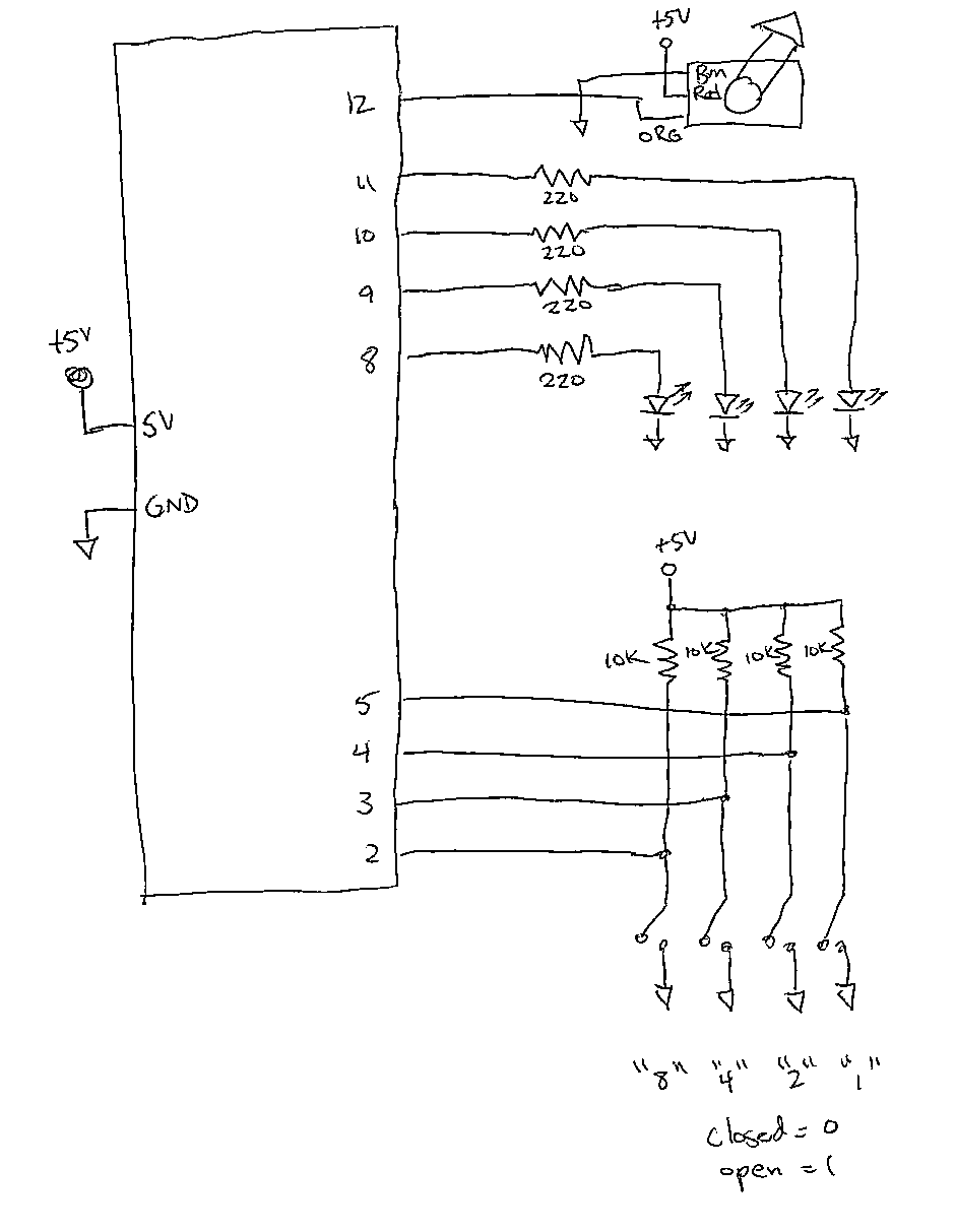
7.24.1. Hand-Drawn Schematic
The following circuit schematic is hand-drawn at a level of detail to reflect test-day time constraints.
7.24.2. Full Reference Source Code
The full code is all in one file Practicum-2016.ino.
1 2 3 4 5 6 7 8 9 10 11 12 13 14 15 16 17 18 19 20 21 22 23 24 25 26 27 28 29 30 31 32 33 34 35 36 37 38 39 40 41 42 43 44 45 46 47 48 49 50 51 52 53 54 55 56 57 58 59 60 61 62 63 64 65 66 67 68 69 70 71 72 73 74 75 76 77 78 79 80 81 82 83 84 85 86 87 88 89 90 91 92 93 94 95 96 97 98 99 100 101 | // Practicum-2016.ino : reference solution for the 2016 16-223 Practicum Examination.
// Garth Zeglin, October 2016.
// Objectives:
// 1. read four switches as a binary value
// 2. display the value on four LEDs
// 3. print the value to the serial port
// 4. move the servo to point an arrow indicator to the value on a physical dial
// ================================================================================
// Import libraries.
#include <Servo.h>
// ================================================================================
// Define constant values.
// Define the physical pin numbers for the inputs and outputs.
const int SWITCH_8_PIN = 2;
const int SWITCH_4_PIN = 3;
const int SWITCH_2_PIN = 4;
const int SWITCH_1_PIN = 5;
const int LED_8_PIN = 8;
const int LED_4_PIN = 9;
const int LED_2_PIN = 10;
const int LED_1_PIN = 11;
const int SERVO_PIN = 12;
// Define the calibration constants for servo scaling. These can be determined
// empirically by testing different values and observing the relationship
// between the switch inputs and the dial position.
const int SERVO_MIN = 180;
const int SERVO_MAX = 33;
// ================================================================================
// Define global variables and objects.
// Create an object to control the servo by declaring it. The Servo C++ class
// is defined in the Servo library.
Servo dial_servo;
// ================================================================================
// Initialize all hardware once after the Arduino starts up.
void setup()
{
// Initialize the serial UART at 9600 bits per second.
Serial.begin(9600);
// Initialize the LED pins for output.
pinMode(LED_8_PIN, OUTPUT);
pinMode(LED_4_PIN, OUTPUT);
pinMode(LED_2_PIN, OUTPUT);
pinMode(LED_1_PIN, OUTPUT);
// Initialize the switch pins for input.
pinMode(SWITCH_8_PIN, INPUT);
pinMode(SWITCH_4_PIN, INPUT);
pinMode(SWITCH_2_PIN, INPUT);
pinMode(SWITCH_1_PIN, INPUT);
// Initialize the servo output pin.
dial_servo.attach(SERVO_PIN);
}
// ================================================================================
// Run one iteration of the main event loop. The Arduino system will call this
// function over and over forever.
void loop()
{
// Read the switch values. Each switch is interpreted as active-high.
int bit8 = digitalRead(SWITCH_8_PIN);
int bit4 = digitalRead(SWITCH_4_PIN);
int bit2 = digitalRead(SWITCH_2_PIN);
int bit1 = digitalRead(SWITCH_1_PIN);
// Calculate the value represented by four binary switch inputs.
int value = (8 * bit8) + (4 * bit4) + (2 * bit2) + (1 * bit1);
// Show the value on the LEDs. Since the output mirrors the input this uses
// the shortcut of writing the input values directly out instead of decoding
// the 'value' variable.
digitalWrite(LED_8_PIN, bit8);
digitalWrite(LED_4_PIN, bit4);
digitalWrite(LED_2_PIN, bit2);
digitalWrite(LED_1_PIN, bit1);
// Print the value out the serial port so it can be seen on the Arduino IDE console.
Serial.print("Decimal value: ");
Serial.println(value);
// Calculate a linearly interpolated dial angle using the map() library function.
int angle = map(value, 0, 15, SERVO_MIN, SERVO_MAX);
// Update the servo command output to move the dial indicator to the value on the scale.
dial_servo.write(angle);
// Delay a short interval to keep the serial stream updating slowly enough to be legible.
// A 50 millisecond delay will show about 20 messages per second.
delay(50);
}
|
7.24.3. Alternate Code Fragments
Several examples of other solution approaches follow. There are many equivalent ways to code the core logic. This is intended to demonstrate other forms you may see.
7.24.3.1. Input Variations
The composition of four bits into a binary value can be written directly using logic operations. This works because digitalRead() always returns either 0 or 1:
value = (bit8 << 3) | (bit4 << 2) | (bit2 << 1) | bit1;
The ternary operator can be used to select terms in an addition or logical-or. This is useful when a boolean value might take on ‘true’ values other than 1. Using addition:
value = (bit8 ? 8 : 0) + (bit4 ? 4 : 0) + (bit2 ? 2 : 0) + (bit1 ? 1 : 0);
Using logical-or:
value = (bit8 ? 8 : 0) | (bit4 ? 4 : 0) | (bit2 ? 2 : 0) | (bit1 ? 1 : 0);
The reading of the input bits and composition into a value could be performed in a single step. Using multiplication and addition:
value = (8 * digitalRead(SWITCH_8_PIN)) + (4 * digitalRead(SWITCH_4_PIN)) + (2 * digitalRead(SWITCH_2_PIN)) + digitalRead(SWITCH_1_PIN);
Using logic operations:
value = (digitalRead(SWITCH_8_PIN) << 3) | (digitalRead(SWITCH_4_PIN) << 2) | (digitalRead(SWITCH_2_PIN) << 1) | digitalRead(SWITCH_1_PIN);
It is also valid to compose the answer in stages using conditional logic:
int value = 0;
if (bit1) value += 1;
if (bit2) value += 2;
if (bit4) value += 4;
if (bit8) value += 8;
7.24.3.2. Output Variations
The LED output values could be decoded from the value by using masks to select individual bits:
digitalWrite(LED_8_PIN, value & 8);
digitalWrite(LED_4_PIN, value & 4);
digitalWrite(LED_2_PIN, value & 2);
digitalWrite(LED_1_PIN, value & 1);
The map() function is a convenient form, but the underlying linear interpolation could be performed directly. The integer math is subject to underflow on division, so care is required in the order of operations:
int angle = value * (SERVO_MAX - SERVO_MIN) / 15 + SERVO_MIN;
There are several approaches to implementing more precise calibration for the mapping between the integer value and the servo angle. One straightforward method is a lookup table using an array:
const int calibration[16] = { 180, 171, 161, 152, 142, 132, 123, 112, 102, 92, 83, 73, 64, 54, 45, 33 };
int angle = calibration[value];
7.24.3.3. Other Variations
In the reference code, the variables bit1, bit2, bit4, and bit8 are declared as integer but only hold a single true or false value. This intent might be more clear if these variable were declared as Boolean using bool:
bool bit8 = digitalRead(SWITCH_8_PIN);
bool bit4 = digitalRead(SWITCH_4_PIN);
bool bit2 = digitalRead(SWITCH_2_PIN);
bool bit1 = digitalRead(SWITCH_1_PIN);
These variables may make the code more legible, but have limited extent and so can be eliminated by combining expressions as follows:
// Calculate the value represented by four binary switch inputs.
int value = (8 * digitalRead(SWITCH_8_PIN)) + (4 * digitalRead(SWITCH_4_PIN)) + (2 * digitalRead(SWITCH_2_PIN)) + digitalRead(SWITCH_1_PIN);
Combining several of these solutions leads to the following compact loop() function:
void loop()
{
  int value = (8 * digitalRead(SWITCH_8_PIN)) + (4 * digitalRead(SWITCH_4_PIN)) + (2 * digitalRead(SWITCH_2_PIN)) + digitalRead(SWITCH_1_PIN);
  digitalWrite(LED_8_PIN, value & 8);
  digitalWrite(LED_4_PIN, value & 4);
  digitalWrite(LED_2_PIN, value & 2);
  digitalWrite(LED_1_PIN, value & 1);
  Serial.print("Decimal value: "); Serial.println(value);
  dial_servo.write(map(value, 0, 15, SERVO_MIN, SERVO_MAX));
  delay(50);
}