4.2.1. Exercise: Bench, Battery, Grid
4.2.1.1. Objective
Learn basic electrical safety, recognize AC and DC sources, learn scale of voltage units.
Caution: this lesson involves measuring dangerous voltages from the AC wall outlets. Please observe meter settings carefully and avoid touching any exposed metal.
4.2.1.2. Steps and observations
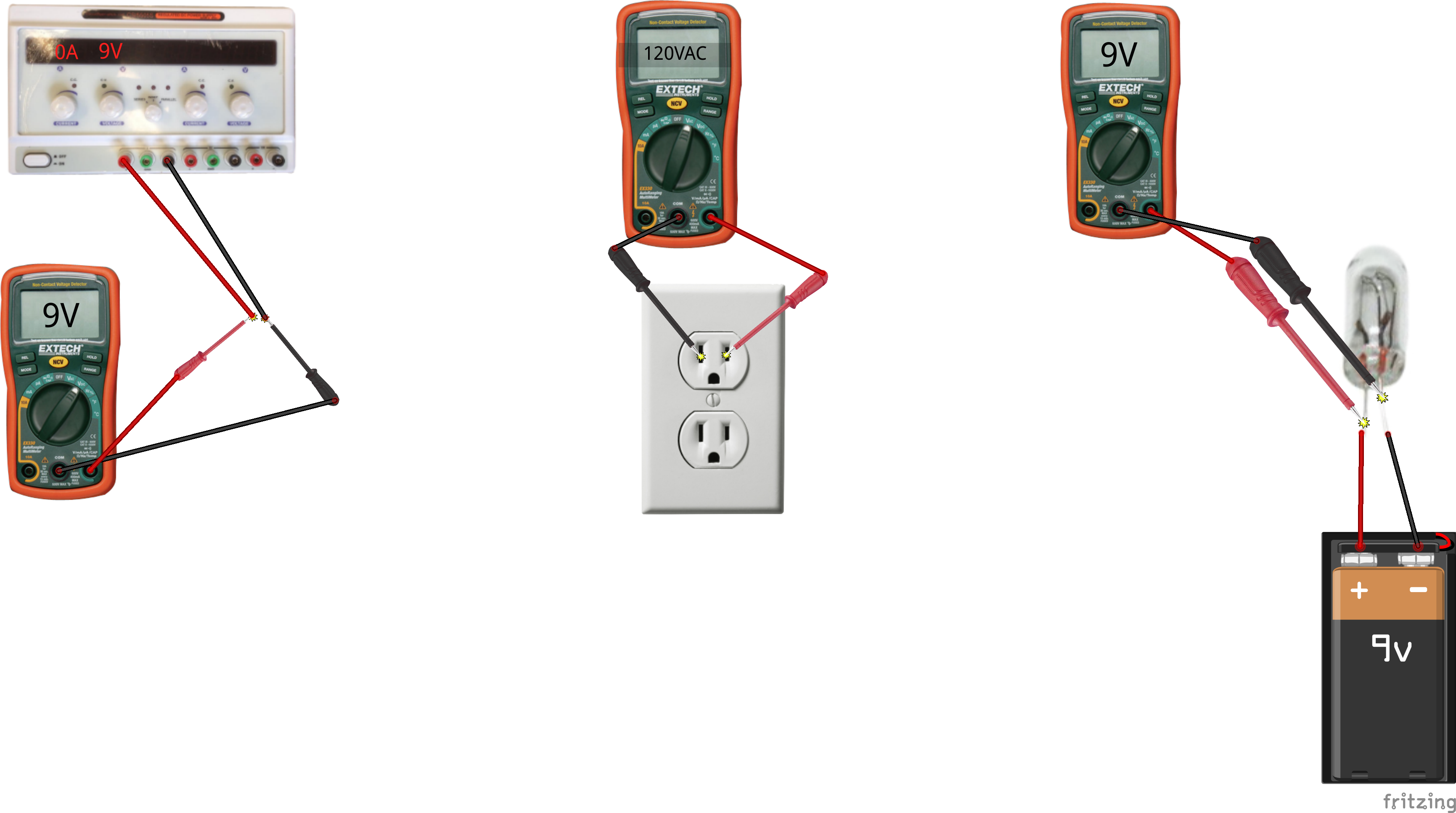
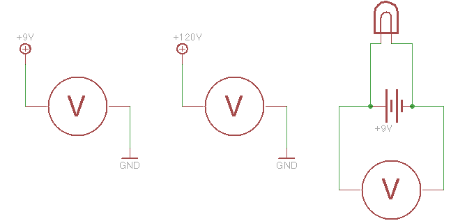
- Set the DMM to VDC. Place probes on a 9V battery as shown. Observe reading. It should show approximately 9 volts.
- Reverse the probes on the battery. Observe reading. It should be the same magnitude with reversed sign.
- Find an incandescent lamp. The lab stocks a grab-bag of lamps with different voltage ratings. Touch leads of lamp to battery contacts. If the lamp doesn’t light, try a smaller one. If it burns out, try a larger one.
- Reverse lamp leads. It should still light: incandescent lamps have no polarity.
- A 9V battery has a low enough voltage that it won’t cause much current flow through dry skin. However, now is a good time to start building the habit of not touching wires or leads, and instead using a meter to check potentials.
- Note: the lab doesn’t have enough power supplies for every student pair to work with their own; please share, multiple circuits can be connected in parallel to each supply.
- Set the DC power supply to 9 Volts.
- Repeat DC voltage measurements between red and black terminals.
- Connect the lamp to the power supply terminals.
- Trying varying the power supply voltage up and down by 2 Volts. Check the voltage using the DMM, not just the power supply display. Observe the response of the lamp.
- Caution: the following step calls for measuring the AC wall outlet voltage. Line power has a high enough voltage to be fatal, so think through how to make contact safely without any chance of exposed metal contacting your body.
- Set the DMM to VAC. Outlet voltage is alternating current for power delivery, so this configures the meter to measure the RMS voltage.
- Double-check that the probe connectors are inserted into the probe ports for voltage measurement, NOT current measurement.
- Carefully touch the probe tips to the metal blade contacts inside the outlet. Observe the reading, it should be approximately 120.
- Repeat between each blade contact and the round grounding contact. Observe readings.
4.2.1.3. Comments
Our typical sensor circuits will all use DC supply voltages ranging from 3.3 to 12V. Our typical actuator circuits will use DC supply voltages from 5V to 12V. Many electronic components have tightly specified supply voltage ranges and will malfunction or be destroyed outside that range.
4.2.1.4. Other Files
- Fritzing file:
bench-battery-grid.fzz - EAGLE file:
bench-battery-grid.sch