4.2.6. Exercise: Switch with pullup
4.2.6.1. Objective
Sense a mechanical action as a varying voltage.
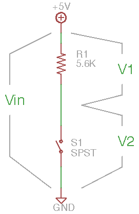
A switch is a special case of a resistor with two states: it has either near-zero resistance when closed or near-infinite resistance when open. A resistor in series with a switch is a very common voltage divider construction in which the pull-up resistor can supply a small current through the switch. If the switch is closed, its resistance is near zero, so the output is connected directly to ground. If the switch is open, the current through the resistor is zero, so there is no voltage drop and the output is pulled up to the supply voltage.
In this example, R1 is the 5.6K pull-up resistor. The exact value of 5.6K is not critical; for our purposes values from 1K to 100K will all work fine to supply a logic signal to an Arduino.
The switch is drawn as a single-pole single-throw switch (SPST) which can only open or close the connection between two pins. It is drawn as a normally-open switch which makes the connection when operated.
4.2.6.2. Steps and observations
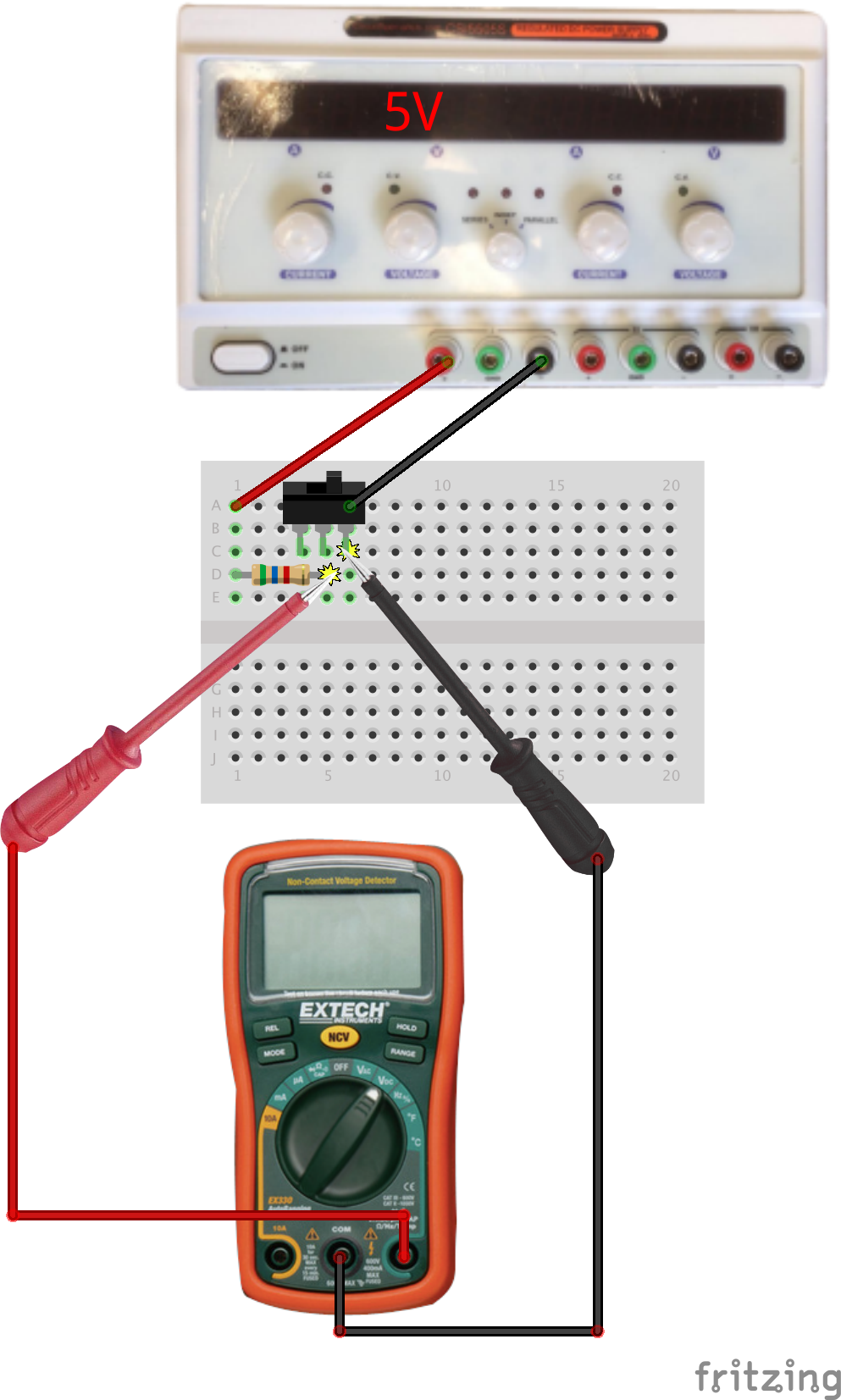
- Set up the resistor and switch on a breadboard; a suggested layout is shown below.
- Measure the exact resistor value.
- Measure the supply voltage.
- Measure the voltage across the switch in both states.
- Measure the current through the resistor in both states. Compare to predictions.
- Create a simple switch from wire and use it to sense some kind of mechanical activity. (Keep this simple, this should only take a minute or two.)
4.2.6.3. Comments
The digital multimeter (DMM)in voltage mode has a very high effective resistance, so it senses a voltage without any significant current flowing through the probes. If the circuit attached to a voltage divider has a resistance closer to the values in the divider, then the analysis is more complicated since current also flows out through the output node. Arduino inputs, both digital and analog, have very high resistance and only very small currents flow into them.
Note that with the switch closed a current flows through the resistor which is entirely dissipated as heat. The higher the resistor value, the smaller the dissipation. In practice, the resistor value isn’t very critical and values from 1K to 100K will work fine with our components. Overall, the higher the value, the lower the power loss, but the weaker the signal available at the output. However, designing electronics for long-life battery operation requires careful attention to minimizing these dissipation losses.
4.2.6.4. Other Files
- Fritzing file:
switch-with-pullup.fzz - EAGLE file:
switch-with-pullup.sch