4.6.9. Answer Key: Electrical Theory Practice
4.6.9.1. Schematic Symbols
Please write one or more names of the component or concept represented by each schematic symbol below. For some cases several hand-drawn variants are included.
Any of the following answers is acceptable:
- resistor
- voltage source, power supply, +5V supply, +9V supply
- ground, 0 Volts
- battery, 9V battery
- LED, light-emitting diode. (Not ‘lamp’ or ‘light’).
- switch, momentary-contact switch, SPST switch, SPDT switch, toggle switch
- potentiometer, variable resistor
- photocell, photoresistor, CdS cell
- speaker
- MOSFET, N-channel MOSFET
- transistor, bipolar transistor, NPN transistor, PNP transistor
- relay
What is the meaning of each of the following acronyms?
| Acronym | Meaning |
|---|---|
| SPST | single-pole single-throw (applied to a switch) |
| SPDT | single-pole double-throw (applied to a switch) |
| LED | light-emitting diode |
| DMM | digital multi-meter |
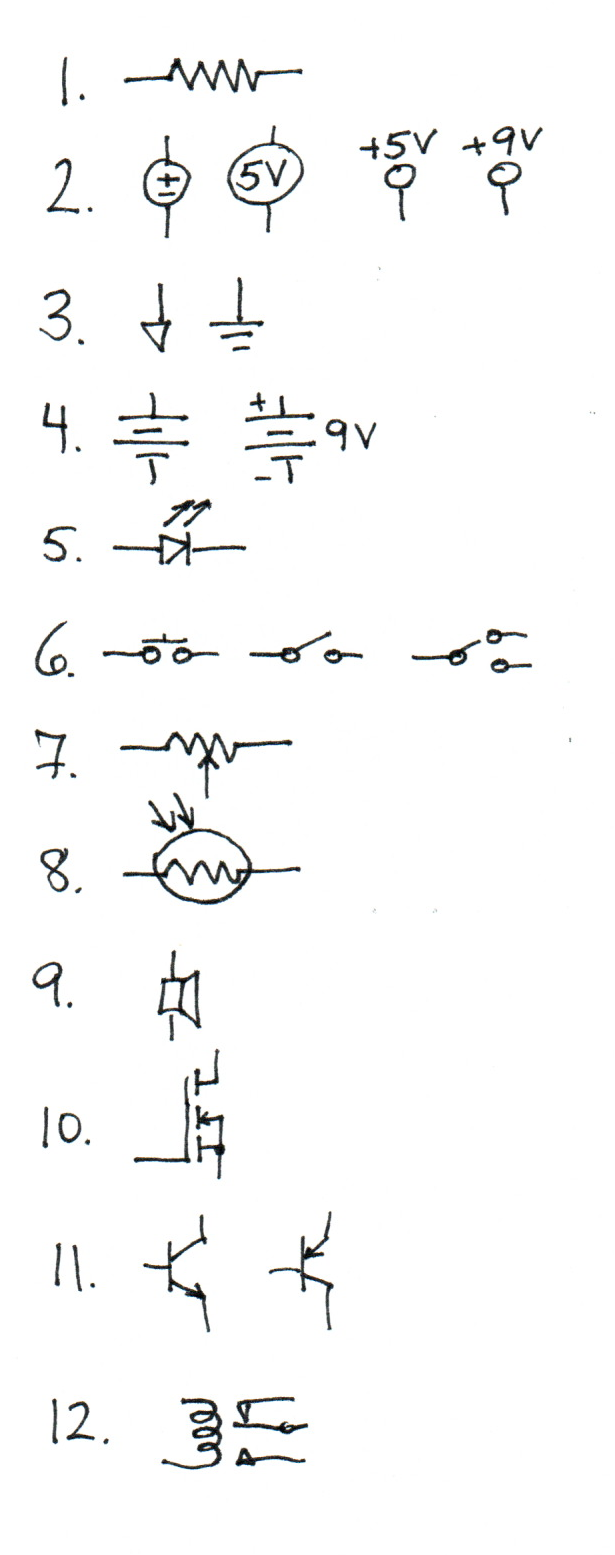
Please label the anode and cathode on the following.
 Anode on the left, cathode on the right.
Is the anode or cathode the more positive terminal when the device is conducting?
Anode
4.6.9.2. Notation
What property and measurement units do each of the following symbols typically represent?
| Symbol | Property | Units |
|---|---|---|
| \(i\) | current | Ampere, milliAmperes |
| \(V\) | voltage | Volt |
| \(R\) | resistance | Ohm, kilo-Ohm |
What do each of these symbols indicate on a schematic?
| Symbol | Meaning |
|---|---|
| \(\Omega\) | Ohms |
| \(K\) | kilo-Ohms |
4.6.9.3. Rules and Measurement
If a voltage \(V\) is measured between two nodes, what is the measurement if the leads are reversed?
\(-V\)What is the canonical form of Ohm’s Law? What are the alternate forms that solve for each dependent variable?
\(V = iR\)\(i = V/R\)\(R = V/i\)What is a concise mathematical statement that can be made about the sum of currents entering a given node?
The currents entering a node sum to zero:
\(\sum i_n = 0\)What is a concise mathematical statement that can be made about the sum of voltages around a circuit loop?
The sum of potentials around a loop is zero:
\(\sum v_n = 0\)If voltage \(V_{xy}\) is measured between points X and Y, and voltage \(V_{yz}\) between points Y and Z, what is the voltage \(V_{xz}\) between points X and Z?
\(V_{xz} = V_{xy} + V_{yz}\)
4.6.9.4. Circuits
Please determine the specific quantities requested for each circuit. Please be sure to include correct units.
Note: each answer below suggests an analysis at a pragmatic level for this course. These are by no means the only approaches.
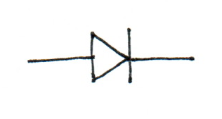
- What is the value of \(i\)?
This is a plain application of Ohm’s Law:
\(i = V / R = 5 / 10000 = 0.0005 A = 0.5 \mathrm{mA}\)
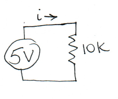
- What are the values of \(i\) and \(V\)?
If you apply the heuristic that resistances in series add:
\(i = V / (R1 + R2) = 5 / 20000 = 0.25 \mathrm{mA}\)
The voltage drop across the lower resistor comes from Ohm’s Law:
\(V = i R = 0.25 \mathrm{mA} * 10000 = 2.5V\)
Fully solving this using only Ohm’s Law is identical to proving the formulas for a voltage divider.
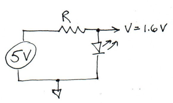
- What is the value of \(R\)?
Loop voltages must sum to zero, so the potential across the resistor:
\(V_r = 5 - 1.6 = 3.4V\)
The resistor value is a plain application of Ohm’s Law:
\(R = V / i = 3.4 / i\)
That’s as much as can be said without a specific value of i. But a typical LED current can run as high as 20 mA, so a reasonable answer could be:
\(R = 3.4 / 0.020 = 170 \Omega\)
This represents a lower bound on reasonable values; lower resistances will allow too much current through the LED, higher values will run it dimmer with more safety margin.
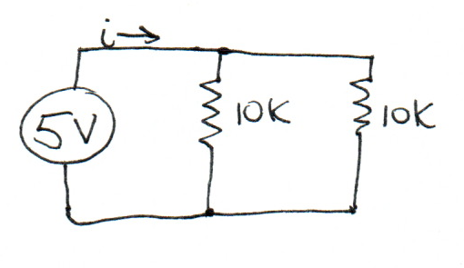
What is the value of \(i\)?
Each resistor has a current according to Ohm’s Law:
\(i_r = V / R = 5 / 10000 = 0.5 \mathrm{mA}\)
The input current is the sum of the two resistor currents:
\(i = i_{r1} + i_{r2} = 0.5 + 0.5 = 1.0 \mathrm{mA}\)
Formally, the resistor currents have negative sign with respect to the node, and the currents sum to zero:
\(i + i_{r1} + i_{r2} = 0\)\(i + (-0.5 \mathrm{mA}) + (-0.5\mathrm{mA}) = 0\)\(i = 1.0 \mathrm{mA}\)
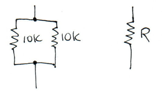
- What is the value of \(R\) for which the component on the right is equivalent to the circuit on the left?
Following on the previous example:
\(R = V / i\)\(R = 5 / 0.001 \mathrm{A}\)\(R = 5000 \Omega\)\(R = 5\mathrm{K}\)The general formula for the combined resistance of two resistors in parallel is:
\(R = (R_1 R_2) / (R_1 + R_2)\)
If the two values are equal, this reduces:
\(R = (R_n R_n) / (2 R_n)\)\(R = R_n / 2\)