14.4. 16-223 Practicum Exam 2017 Sample Solution
Following is a sample solution for the 16-223 Practicum Exam 2017: Metronome. There are multiple valid implementation choices which received full credit, but this is one recommended approach.
Contents
14.4.1. Input/Output Circuit
Notes:
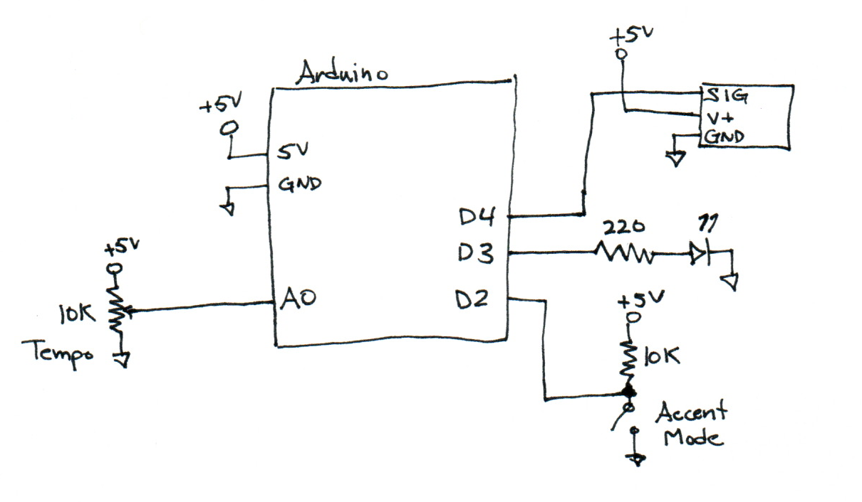
- The potentiometer is wired across +5 and GND to provide the full input range to A0.
- The slide switch is used as an SPST switch with a pullup resistor.
- The LED includes a ‘ballast’ dropping resistor in series. It is wired with to GND, yielding positive logic (HIGH==on).
- Omitting the dropping resistor entirely cost points; even though that can work with the current-limited Arduino pins, it is not a recommended practice as it can easily cause the Arduino to exceed its output current limits.
Some alternatives:
- The switch could be used as SPDT, with the pole pin attached to D2 and the two throw pins attached to +5V and GND, respectively. This was a common solution and given full credit, but has the disadvantage that the pole can float very briefly while the switch is in transition, increasing the chance of bounce or noise. This is generally discouraged, but not a problem for this application.
- The LED could be wired instead to +5V and used in a negative-logic mode (LOW==on).
- The potentiometer could be instead used as a variable resistor in series with another resistor to form a voltage divider. This does reduce the available voltage range, and changes the answer to analysis question #3.
14.4.2. Arduino Sketch Source Code
The following sketch includes detailed comments, although these were not required for the exam solution. It issues just one motion command per beat, and uses delay() for timing. This is not the most smooth or precise solution, but is one of the fastest to program.
Some improved alternatives:
- Generate more intermediate servo commands for smoother beat sweeps. This requires some care to avoid numeric underflow; delayMicroseconds() might be better than delay() for small step intervals.
- Use the real-time micros() clock to test when the next beat time has arrived. This is potentially more precise since it eliminates some effects of the variant execution time of the logic code paths.
1 2 3 4 5 6 7 8 9 10 11 12 13 14 15 16 17 18 19 20 21 22 23 24 25 26 27 28 29 30 31 32 33 34 35 36 37 38 39 40 41 42 43 44 45 46 47 48 49 50 51 52 53 54 55 56 57 58 59 60 61 62 63 64 65 66 67 68 69 70 71 72 73 74 75 76 77 78 79 80 81 82 83 84 85 86 87 88 89 90 91 92 93 94 95 96 97 98 99 100 101 102 103 104 105 106 107 108 109 110 111 112 113 114 115 116 117 118 119 120 121 122 123 124 125 126 | // Practicum-2017.ino : reference solution for the 2017 16-223 Practicum Examination.
// Garth Zeglin, October 2017.
// Objectives:
// 1. read a tempo from a potentiometer as an analog value
// 2. read an accent mode from a switch (1/3 or 1/4 beat rate)
// 3. beat time with a servo
// 4. highlight accent beats with an LED flash
// 5. print the tempo value to the serial port
// ================================================================================
// Import libraries.
#include <Servo.h>
// ================================================================================
// Define constant values.
// Define the physical pin numbers for the inputs and outputs.
const int TEMPO_INPUT = A0;
const int ACCENT_SWITCH_PIN = 2;
const int ACCENT_LED_PIN = 3;
const int SERVO_PIN = 4;
// Define the minimum mandated tempo range.
const int MIN_TEMPO = 40;
const int MAX_TEMPO = 180;
// ================================================================================
// Define global state variables and objects.
/// Total beat count.
long beats = 0;
/// Create an object to control the servo by declaring it. The Servo C++ class
/// is defined in the Servo library.
Servo beat_servo;
// ================================================================================
/// Initialize all hardware once after the Arduino starts up.
void setup()
{
// Initialize the serial UART at 9600 bits per second.
Serial.begin(9600);
// Initialize the LED pin for output.
pinMode(ACCENT_LED_PIN, OUTPUT);
// Initialize the switch pin for input.
pinMode(ACCENT_SWITCH_PIN, INPUT);
// Initialize the servo output pin by connecting with the servo control object.
beat_servo.attach(SERVO_PIN);
}
// ================================================================================
/// Run one iteration of the main event loop. The Arduino system will call this
/// function over and over forever.
void loop()
{
// Read the user inputs.
int tempo_input = analogRead(TEMPO_INPUT);
int accent_mode = digitalRead(ACCENT_SWITCH_PIN);
// Calculate a tempo in BPM from the raw analog value. Note that the active
// range is set slightly narrower than the full potentiometer range to
// guarantee reaching each limit. This isn't strictly necessary, but makes
// the result more tolerant to component variation.
int tempo_bpm = map(tempo_input, 0, 1023, MIN_TEMPO-10, MAX_TEMPO+10);
// Limit the possible tempo values to the prescribed range.
tempo_bpm = constrain(tempo_bpm, MIN_TEMPO, MAX_TEMPO);
// Calculate the number of milliseconds per beat. There are 60000
// milliseconds in a minute, so this is
// (msec/minute) / bpm = (msec / minute) * (minute / beat)
// = msec / beat
long msec_per_beat = 60000L / tempo_bpm;
// Configure the accent timing.
int accent_interval;
if (accent_mode) accent_interval = 3;
else accent_interval = 4;
// Command the servo to either an even or odd beat position. The servo will
// start to move toward that position while the code continues. A more
// graceful solution might generate a smooth path at a rate depending on
// tempo, but this solution is sufficient to indicate the timing.
if ((beats % 2) == 0) {
beat_servo.write(120);
} else {
beat_servo.write(60);
}
// If the current beat is an accent beat, light the LED.
if ((beats % accent_interval) == 0) {
digitalWrite(ACCENT_LED_PIN, HIGH);
} else {
digitalWrite(ACCENT_LED_PIN, LOW);
}
// Produce the visible report.
// This is the one required output:
Serial.print("Tempo: ");
Serial.print(tempo_bpm);
Serial.print(" BPM");
// Print additional values for debugging.
Serial.print(" Raw tempo input: ");
Serial.print(tempo_input);
Serial.print(" interval: ");
Serial.print(msec_per_beat);
Serial.print(" beat: ");
Serial.print(beats);
Serial.println();
// Increment the beat counter.
beats++;
// Delay for the current beat interval. Since nothing in the code takes very
// long, this will be the dominant timing delay and the metronome will be
// sufficiently accurate. A more precise implementation might use the
// microseconds clock value from micros() to test when the interval had
// elapsed independent of execution time..
delay(msec_per_beat);
}
|
14.4.3. Circuit Analysis Questions
Please answer the following electrical questions about your implementation. In each case, please show your work and computed value, including units.
- How do you calculate the expected current through the LED while it is on, assuming it has a typical 1.6V drop?
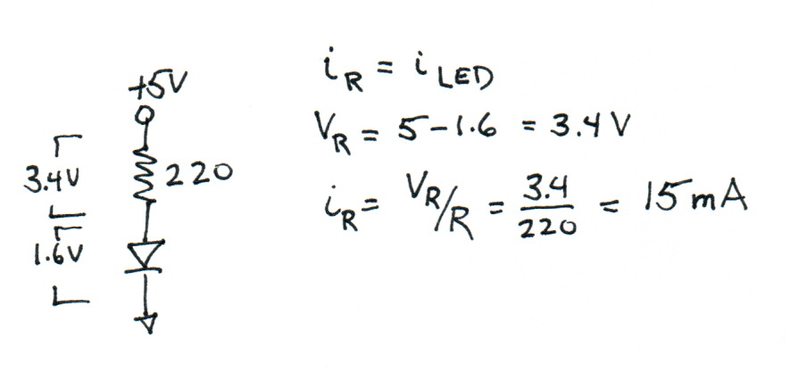
Explanation:
- The current through the LED and resistor must be the same, as per the KCL rule.
- The sum of the resistor and and LED voltage drops must be 5V, as per the KVL rule.
- The resistor voltage drop is thus 3.4V, and the resistor current can be found by application of Ohm’s Law.
- How do you calculate the power consumed by the LED while it is on?
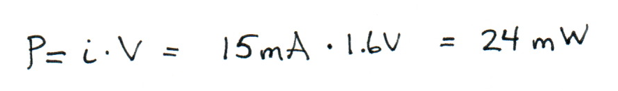
Explanation: the LED power is the LED current times the voltage drop across the LED.
- How do you calculate the power dissipated by the potentiometer in your implementation? Does it vary with the position of the knob?
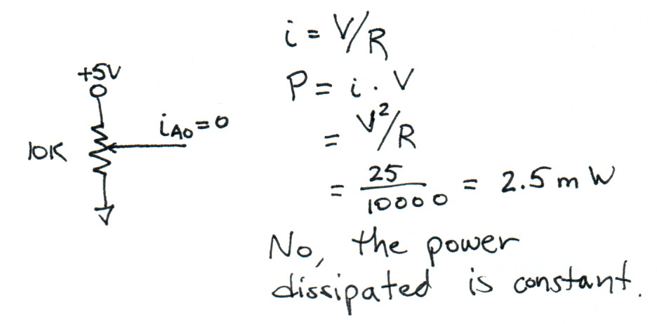
Explanation:
- The A0 analog input has high input impedance and essentially no current passes into it.
- The potentiometer is wired directly across +5 and GND, so the current through it must be constant.
- The power is then the current times the voltage drop, which can be solved using Ohm’s Law to \(P=V^2/R\) and the value computed.
- Note that moving the wiper of the potentiometer in this application doesn’t change the base resistance; it is sampling different points along the voltage gradient formed within the potentiometer.
- Note that other potentiometer circuits are possible, and might have a different answer.