14.3. 16-223 Practicum Exam 2017: Metronome
Please write your name here:
Please quickly read through all the instructions before beginning.
14.3.1. Objectives
- Implement a digital metronome with a physical beat indicator, selectable accent indicator, and adjustable tempo. The specific requirements for the device are specified in some detail below.
- Document the work with a schematic circuit diagram.
- Answer a few related circuit analysis questions.
Once you have physically built, programmed, and tested your device, please call over one of your instructors for live testing. We recommend that you use time spent waiting for review to complete the documentation portion.
One caution: if you get stuck debugging, please consider when to stop and complete the documentation.
14.3.2. Summary Diagrams
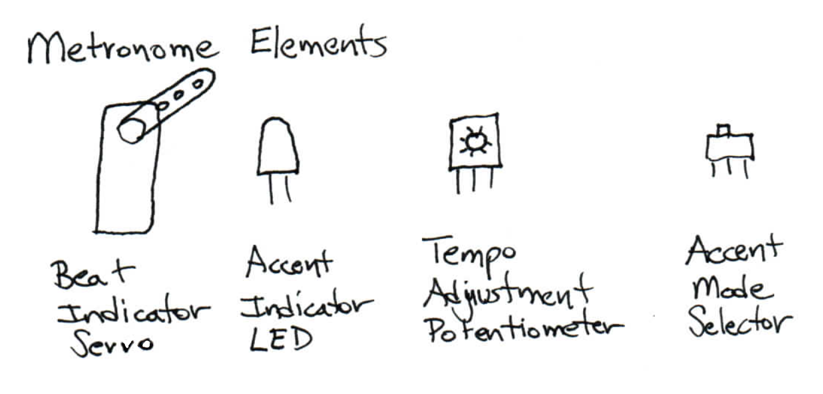
The key physical elements of the metronome demo: a servo used as a beat indicator, an LED to indicate accents, a potentiometer to set tempo, and a switch to select a 1/3 or 1/4 accent ratio.
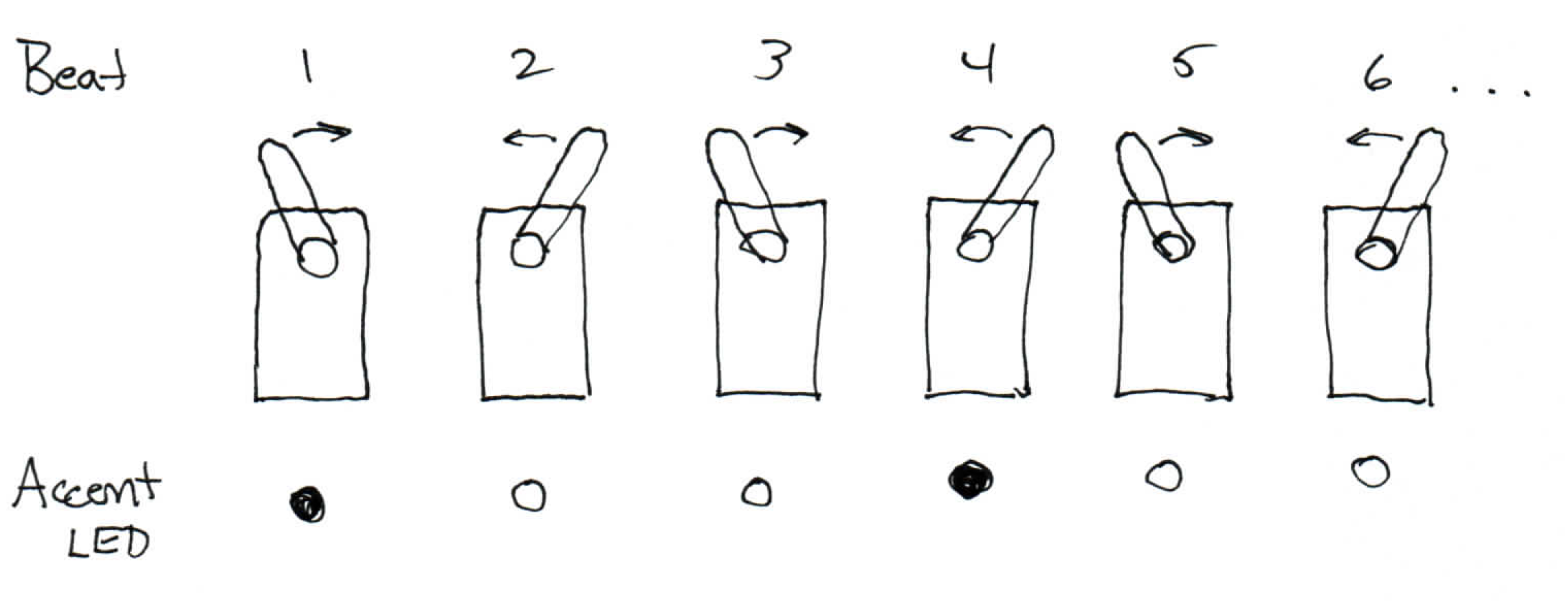
An example of metronome operation at the 1/3 accent ratio: six beats are shown, with the servo horn swinging in alternate directions, and the accent indicator lighting up every third beat.

The demo is inspired by a mechanical metronome which beats out a constant tempo, commonly used for musical practice. The pendulum moves back and forth at a constant rate. Adjusting the position of the weight varies the tempo. Image credit: Vincent Quach [CC BY-SA 3.0], via Wikimedia Commons.
14.3.3. Requirements
The device should:
- Use the kit micro-servo for the beat indicator. When running, it should swing once per beat at a constant tempo. I.e., a full cycle returning to the start is two beats.
- Use a potentiometer for tempo adjustment. A user should be able to set the device to any tempo between 40 beats per minute (BPM) and 180 BPM.
- Use a slide switch to set the accent interval to either three or four beats.
- Use an LED as an accent indicator. It should visibly light only on accented beats, in time with the beat indicator.
- Print the current tempo to the serial console every beat. The value should match the observable physical tempo within reasonable perception; like the mechanical metronome, some small absolute error is tolerable if the beat is steady.
14.3.4. Rules
- We will provide a potentiometer.
- Otherwise, use only parts from your class kit, including an Arduino. If you are missing a necessary part, we have a limited supply of spares; please raise your hand to request a replacement.
- You will need a laptop to program your Arduino and display serial output; you may use your own or a cluster machine.
- You may freely consult your notes, books, the course web site, or any online sources. You may freely use code or circuit examples that you find from these resources. You are not required to cite sources.
- You may not consult your classmates or any other person. No collaboration of any kind is permitted whether in-person or via website, email, chat or other digital means.
- If you have a question, raise your hand and we’ll swing by. Good luck!
14.3.5. Procedure
The first step is to build a circuit on your breadboard which implements the inputs and outputs for the Arduino.
Electrical Implementation
Please build a circuit with the following connected to your Arduino using proper circuit practices:
- A potentiometer to use as the tempo input.
- A slide switch to use as the accent mode input.
- An LED to use as the accent indicator output. You may not use the onboard LED, please provide your own.
- A micro-servo to use as the beat indicator output. It may be powered directly from the Arduino.
Programming
The second step is to program and test the software to run the demo. We recommend that you start with an existing sketch and modify it; this will help avoid a number of potential trivial errors.
The sketch should implement the following:
Moving the servo to beat time at a steady rate. (Remember, each beat is one swing or half-cycle.)
Allowing the user to set a tempo via the potentiometer over at least the 40 to 180 BPM range. The tempo can be integral, no fractions are needed. The device should operate properly for any potentiometer position.
Allowing the user to set the accent ratio to either 1/3 or 1/4 using the switch.
Flashing the LED on every third or fourth beat as specified by the user.
Printing the current tempo to the serial monitor at least once per beat, in units of beats-per-minute. Please follow this format:
Tempo: 120 BPM
You may print additional information on the same line if you wish as long as the tempo is clearly legible.
Testing and Demonstration
- Please carefully test your sketch. Please make sure your input devices are firmly seated and easily accessible to the instructors for testing. Please make sure the Arduino IDE serial monitor is clearly visible on your laptop screen.
- When you are ready for review, please raise your hand. An instructor will photograph your breadboard and test your circuit. Please place your test paper with your name adjacent to your breadboard so your name is clearly visible in the photograph.
- If your instructors find a flaw in the implementation, you will be given one try to correct your result, with some loss of points. Please test carefully.
- If you run out of time, we will test what you have completed and award partial credit as appropriate. However, if the end is approaching, please make a careful allocation of time between debugging and completing the documentation.
- Please leave your circuit intact for grading inspection after the exam. Please return any unused parts to your kit box and leave both on your table; your instructors will return your breadboard to your box.
Documentation
The final step is to document your work.
Please hand-draw a schematic of your circuit on the back of this page, following the graphic conventions you have been seeing in the exercises. The Arduino can be simplified to a box including only the pins actually used by the circuit. Be sure to carefully label each pin and component value; the schematic should have enough detail that someone skilled in the art could exactly replicate your circuit topology. Note that it is not necessary to show the breadboard layout, only the schematic symbols and connections.
Please email a copy of your .ino sketch file to garthz@cmu.edu as an attachment.
Please answer the following electrical questions about your implementation. In each case, please show your work and computed value, including units.
How do you calculate the expected current through the LED while it is on, assuming it has a typical 1.6V drop?
How do you calculate the power consumed by the LED while it is on?
How do you calculate the power dissipated by the potentiometer in your implementation? Does it vary with the position of the knob?
14.3.6. Grading
Full credit: The machine works exactly as specified and is constructed using solid technique. A user can adjust the potentiometer and observe the full tempo range. The switch can select the accent ratio at any tempo. The accent flash is at the correct rate and legibly in time with the beat. The serial monitor shows the correct tempo. The machine updates continuously so any switch and potentiometer changes immediately take effect. The schematic is detailed and the circuit follows good practices. The analytic answers show correct application of electrical theory.
Partial credit:
| 25% | inputs and outputs are wired properly |
| 25% | device performs correctly |
| 25% | compilable Arduino code that satisfies the prompt |
| 25% | documentation and analysis are accurate |
14.3.7. Test Paper
The following document was provided on paper on test day: practicum-2017.pdf