14.2. 16-223 Practicum Exam Re-test 2016: Math Machine
Please write your name here:
Please quickly read through all the instructions before beginning.
14.2.1. Objective
Implement a switchable multiplication and addition machine with two separate readouts of the value, using only parts from your class kit. The requirements for the device are specified in some detail below.
Once you have physically built, programmed, and tested your device, please call over one of your instructors for live testing. We recommend that you use time spent waiting for review to complete the documentation portion. One caution: if you get stuck debugging, please consider when to stop and complete the documentation.
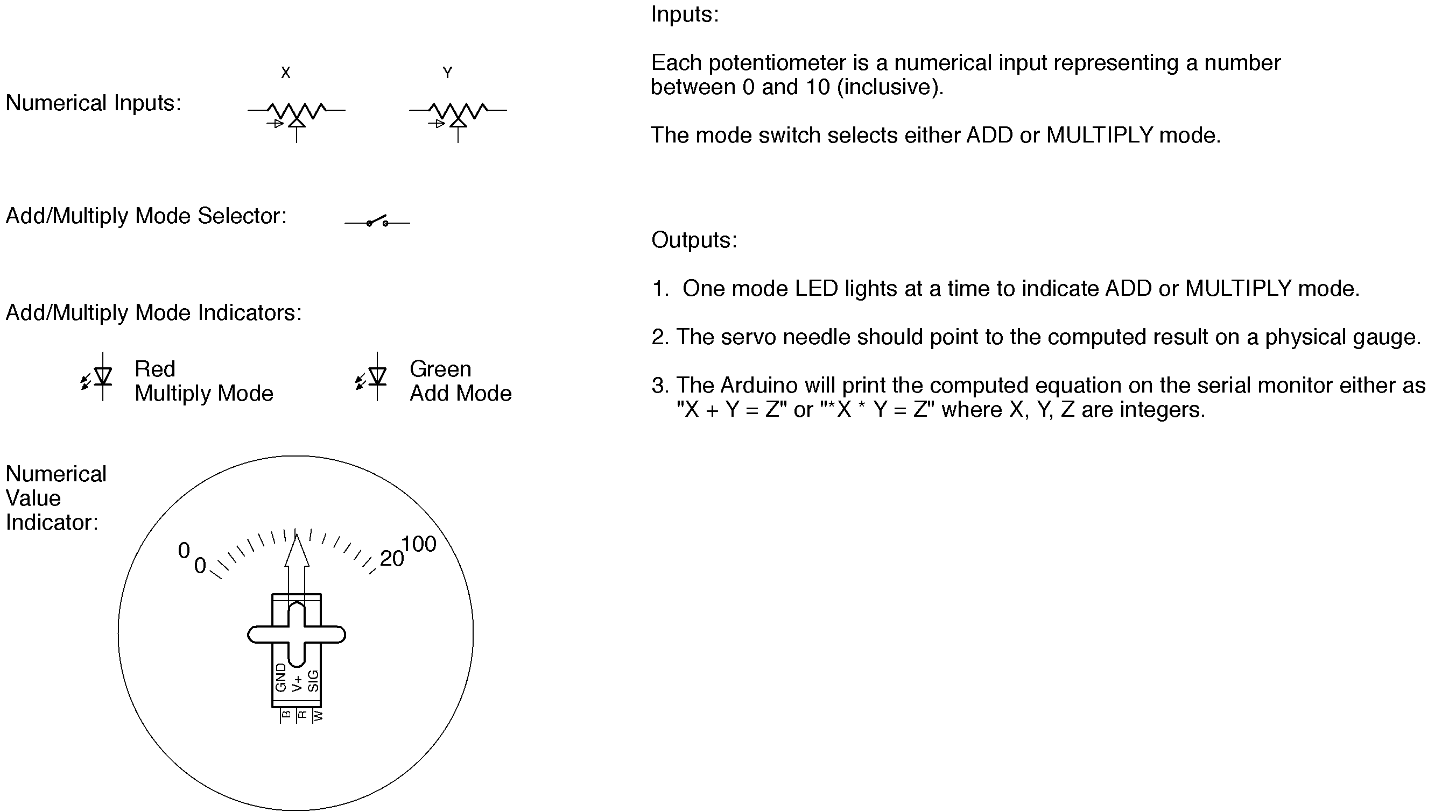
14.2.2. Summary Diagram of Demo
14.2.3. Rules
- Use only parts from your class kit, including an Arduino. If you are missing a necessary part, we have a limited supply of spares; please raise your hand to request a replacement.
- You will need a laptop to program your Arduino and display serial output; you may use your own or a cluster machine.
- You may freely consult your notes, books, the course web site, or any online sources. You may freely use code or circuit examples that you find from these resources. You are not required to cite sources.
- You may not consult your classmates or any other person. No collaboration of any kind is permitted whether in-person or via website, email, chat or other digital means.
- If you have a question, raise your hand and we’ll swing by. Good luck!
14.2.4. Procedure
The first step is to build a circuit on your breadboard which implements the following inputs and outputs for your Arduino: two potentiometers, one switch, two LEDs, and a hobby servomotor. We will also observe the Arduino IDE serial monitor output on your laptop screen. Please observe proper circuit practices as we have previously discussed in the exercises.
Electrical Implementation
- Please build a circuit with two potentiometers which will serve as numerical input to your Arduino, and a slide switch that will change the machine’s output mode between multiplication and addition. Each potentiometer will have a value range of the integers 0 through 10, where the most counterclockwise position yields 0 and the most clockwise yields 10.
- Please build a circuit with two LEDs to indicate the mode that the machine is in; when the machine is switched into multiplication mode, a red LED should be illuminated, and when the machine is switched into addition mode a green LED should be illuminated. The LEDs must be software-controlled, not simply wired directly to the slide switch circuit.
- Please attach the blue micro-servomotor from your kit to be powered and controlled by the Arduino. We will supply you with a cardboard gauge cutout and a cardboard arrow to attach to a servo horn and place on the output shaft. When the machine is switched into multiplication mode the range will run 0–100, and when it is in addition mode the range will run 0–20. (These ranges are chosen because the minimum product is 0x0=0, and the maximum product is 10x10=100, while the minimum sum is 0+0=0 and the maximum sum is 10+10=20.)
Programming
The second step is to program and test the software to run the demo. We recommend that you start with an existing sketch and modify it; this will help avoid a number of potential trivial errors.
The machine has three different outputs that all run simultaneously, with a display updated no less often than 10 times per second. The sketch should implement the following:
- Serial monitor feedback. When the machine is switched to multiplication mode, the Arduino IDE serial monitor should continuously display the message “X * Y = Z” where X and Y are integer values between 0 and 10 based on the potentiometer positions and Z is their product. When the machine is in addition mode, the Arduino IDE serial monitor should continuously display the message “X + Y = Z” where X and Y are integer values between 0 and 10 based on the potentiometer positions and Z is their sum. Each update should appear on a new line.
- LED mode display. When the slide switch is instructing the machine to use addition mode, the green LED should be illuminated (and the red LED dark). When the slide switch is instructing the machine to use multiplication mode, the red LED should be illuminated (and the green LED should be dark).
- Numeric pointer display. The servo with attached pointer should continuously indicate the output value on the appropriate scale for the mode the math machine is in. Please calibrate the output position sufficiently to avoid confusion, i.e., the point should be close enough to the correct number that the reading is unambiguous.
Testing and Demonstration
- Please carefully test your sketch. Please make sure your switches and potentiometers are firmly seated and easily accessible to the instructors for testing. Please make sure the Arduino IDE serial monitor is clearly visible on your laptop screen.
- When you are ready for review, please raise your hand. An instructor will photograph your breadboard and test your circuit. Please place your test paper with your name adjacent to your breadboard so your name is clearly visible in the photograph.
- If your instructors find a flaw in the implementation, you will be given one try to correct your result, with some loss of points. Please test carefully.
- If you run out of time, we will test what you have completed and award partial credit as appropriate. However, if the end is approaching, please make a careful allocation of time between debugging and completing the documentation.
- Please leave your circuit intact for grading inspection after the exam. Please return any unused parts to your kit box and leave both on your table; your instructors will return your breadboard to your box.
Documentation
The final step is to document your work.
- Please hand-draw a schematic of your circuit on the back of this page, following the graphic conventions you have been seeing in the exercises. The Arduino can be simplified to a box including only the pins actually used by the circuit. Be sure to carefully label each pin and component value; the schematic should have enough detail that someone skilled in the art could exactly replicate your circuit topology. Note that it is not necessary to show the breadboard layout, only the schematic symbols and connections.
- Please email a copy of your .ino sketch file to garthz@cmu.edu as an attachment.
14.2.5. Grading
Full credit: The machine works exactly as specified and is constructed using solid technique. A user can arrange the switch and potentiometers in any configuration and observe the correct sum or product displayed on the servomotor gauge, the equation with correct values is shown in the serial output, and the appropriate LED is lit. The machine updates continuously so any switch and potentiometer changes immediately take effect. The schematic is detailed and the circuit follows good practices.
Partial credit:
| 15% | potentiometers and switch wired properly |
| 5% | LEDs wired properly |
| 10% | serial feedback working (formatted as specified) |
| 20% | servomotor “gauge” points to correct position |
| 35% | compilable Arduino code that satisfies the prompt |
| 15% | schematic is accurate and legible |
14.2.6. Test Paper
The following document was provided on paper on test day: practicum-retest-2016.pdf