What technical limitations did you discover during the visit?
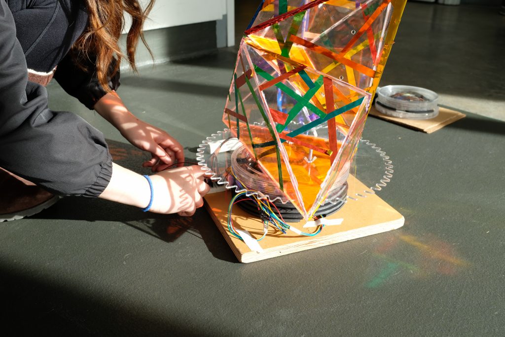
Further rigidity between the prism structure and the base can ensure less concern during transportation, though all pieces managed to go through safely this past Saturday without any bracing on the van. Upon arrival at the museum, our power sources (battery packs) performed as expected, making our design easy to move when we decided to change sites. There wasn’t a strong enough connection between the stepper motors and the gear, thus the stepper motor broke free from its connection and our fragmented model was unable to rotate at the museum. The calibration on the PIR also took too long, thus rendering the design “dead” for long periods of time. Lastly, the LED light was overridden by the museum’s natural light, thus a shift to some other kind of responsive feedback is needed in replacement of LEDs.
In what ways did children and adults find a moment of delight in your project?
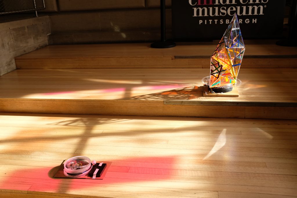
 The natural lighting in the room allowed for the projection of the metallic pieces in the model to shine on the walls, floor and ceiling. The intricate nature of the design along with the strips of color spread across it caught the attention of both the adults and the children. The floor disk also attracted some attention by children in the water play room, and perhaps need to be better applied to have the same effect in the lobby.
What aspects of the observed interactions were surprising to you?
On several occasions both adults and children would approach the design, but shortly after walk away as it looked too delicate and sharp to interact with. Surprisingly our largest concern, children touching and destroying the modules, did not actually happen. Instead, because of the sharp edges of the design and glass-like, delicate appearance, children didn’t seem to bother touching the module. Instead they took interest in the light up circle that we had placed in front of the design. Tapping the circle a few times there seemed to be the expectation of movement being triggered by their tapping, as the children would look up a few times after a tap. However due to the PIR recalibration and the stepper to gear connection being broken, nothing occurred in the disk or prism rotation and the children immediately lost interest thereafter.
What are additional or different interaction features which would help visitors perceive more of the delight, magic, function, or purpose?
- Shift from LED to Sound or other kinds of responsive feedback on the floor disks would encourage interaction + more disks that can relate better to the museum floor circular lights
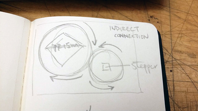
- Use 2 gears rather than one so the stepper is not carrying direct load of the prism but rather an indirect load of rotating a gear that would rotate the prism gear.
- More thought out coding of the behavior of the prism so that it is constantly rotating at a slow rate, and then shift at a faster rate when the person is sensed by the PIR at certain distances.
How does this visit change your vision of the fully realized project?
We were initially planning on having three modules rotate about one another. However, after seeing how one stand alone in the museum, we realized that having one, nicely curated module rotating on it own would be far more interesting than three modules done at a lower quality.
With the busy nature of the museum visitors, we also realized that having the module rotate consistently at a slow speed would be needed to catch the attention of the visitors. Otherwise, as we observed, the module was looked upon as an art installation and given very little interest.
As the nature of children at the museum seemed to revolve around curiosity and discovery, it became evident that the most important aspect of the design is its ability to be interactive with its users. Children don’t just want to look, they want to touch and explore. Creating more floor modules that are set at distances in association with the pre-programmed distance indicators for different rotations will become crucial in making the children feel like tapping or moving to the different floor modules moves the fragmented module.
Revision Plan
What will it take to resolve known technical limitations?
To resolve the technical limitations of movement of the stepper and accuracy of the pir sensor, the programming of the Arduino must be revised. One big issue with the inaccuracy of the sensor was the delay time due to the calibration time used in the function. Because the pir was programmed to calibrate between signals, the overall system was delayed in movement from 30 seconds to a minute. Therefore, the calibration time must be decreased or removed if possible. In terms of the movement of the fragmented module in sync with the touching of the floor modules, certain distances need to be defined in the Arduino script so that when a certain distance is achieved, the stepper will be programmed to move a certain degree in accordance with the distance of the person sensed from the pir.
One thing that was noticed after installing the pir sensor was that the pir senses movement from a very wide angle. To ensure that the movement detected is contained in a certain area, paper might need to be used to make that angle smaller.
Also an additional gear piece needs to be added so that the stepper is affecting the prism indirectly rather than a direct connection where the force at play would be much higher than indirectly, and would cause an increased chance in the stepper to gear connection breaking. A more concealed base also aids in providing a “finished” look to the project.
How does the fundamental experience need to be modified?
The overall experience needs to be modified to include a more interactive component (the floor disks). We may also look into making the journey / path to discovery of the fragmented modules something more intriguing. Perhaps through using the existing lights in the floor of the lobby to pull the children in towards our design.
What new capability will you add beyond the initial objectives?
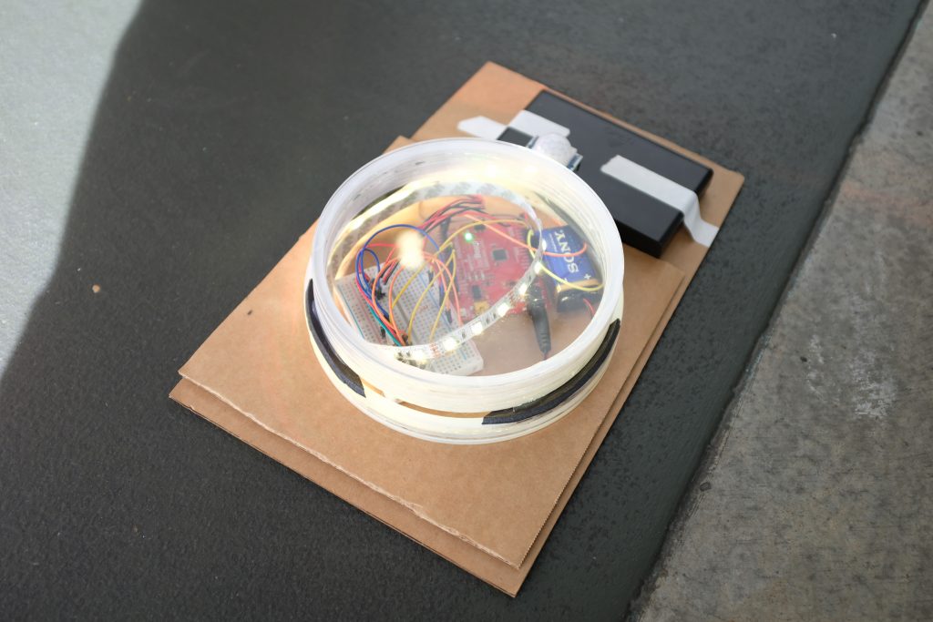
One new capability that will be added to the floor module pieces (which are the pieces that the children really interact with) will be sound. Because there is a lot of ambient lighting in the lobby, the led strips that were previously installed in the floor modules were difficult to see and thus a waste of energy if they have no effect. Though the lobby is a bit loud, we aim to test short sounds that can surprise the children who interact with the floor modules with the hope that the sound might excite them to explore the other floor modules even further.
Revised Script for the Stepper
</pre>
#include <Stepper.h>
int pos = 0;
int calibrationTime=30; //time for sensor to calibrate
long unsigned int lowln; // sensor outputs a low impulse
long unsigned int pause = 5000; //miliseconds the sensor has to be low before all motion is assumed to be stopped.
boolean lockLow=true;
boolean takeLowTime;
int pirPin = 6; // connects to PIR output
int pirPos = 0;
// StepperSweep - move a stepper motor at different rates
//
// Copyright (c) 2016, Garth Zeglin. All rights reserved. Licensed under the
// terms of the BSD 3-clause license as included in LICENSE.
//
// This program assumes that:
//
// 1. A A4988 stepper motor driver is connected to pins 2 and 3.
// 2. A control potentiometer can vary the voltage on A0.
// 3. The serial console on the Arduino IDE is set to 9600 baud communications speed.
// ================================================================================
// Define constant values and global variables.
// Define the pin numbers on which the outputs are generated.
#define DIR_PIN 2 // The direction pin controls the direction of stepper motor rotation.
#define STEP_PIN 3 // Each pulse on the STEP pin moves the stepper motor one angular unit.
#define ENABLE_PIN 4 // Optional control of the driver power.
// ================================================================================
// Configure the hardware once after booting up. This runs once after pressing
// reset or powering up the board.
void setup(void)
{
Serial.begin(9600); //begins serial communication
pinMode(pirPin, INPUT);
pinMode(pirPos, OUTPUT);
digitalWrite(pirPos, HIGH);
//give sensor time to calibrate
Serial.println("calibrating sensor");
for(int i = 0; i<calibrationTime; i++){
Serial.print(calibrationTime - i);
Serial.print("-");
delay(1000);
}
Serial.println();
Serial.println("done");
//make sure the PIR output is low before ending setup
while (digitalRead(pirPin)==HIGH){
delay(500);
Serial.print(".");
}
Serial.print("SENSOR ACTIVE");
// Initialize the stepper driver control pins to output drive mode.
pinMode(DIR_PIN, OUTPUT);
pinMode(STEP_PIN, OUTPUT);
pinMode(ENABLE_PIN, OUTPUT);
// Drive the /ENABLE pin low to keep the motor always energized.
digitalWrite(ENABLE_PIN, LOW);
}
/****************************************************************/
/// Rotate the stepper motor a specified distance at constant speed. It does
/// not return until the motion is complete, e.g. it 'blocks' for the duration.
///
/// \param steps angular distance to move; the sign determines the direction,
/// but the precise angle depends upon the driver microstepping
/// configuration and type of motor.
///
/// \param speed speed in steps/second
void rotate_stepper(int steps, float speed)
{
// Configure the direction pin on the stepper motor driver based on the sign
// of the displacement.
int dir = (steps > 0)? HIGH:LOW;
digitalWrite(DIR_PIN, dir);
// Find the positive number of steps pulses to emit.
int pulses = abs(steps);
// Compute a delay time in microseconds controlling the duration of each half
// of the step cycle.
// microseconds/half-step = (1000000 microseconds/second) * (1 step/2 half-steps) / (steps/second)
unsigned long wait_time = 500000/speed;
// The delayMicroseconds() function cannot wait more than 16.383ms, so the
// total delay is separated into millisecond and microsecond components. This
// increases the range of speeds this function can handle.
unsigned int msec = wait_time / 1000;
unsigned int usec = wait_time - (1000*msec);
// Print a status message to the console.
Serial.print("Beginning rotation of ");
Serial.print(steps);
Serial.print(" steps with delay interval of ");
Serial.print(msec);
Serial.print(" milliseconds, ");
Serial.print(usec);
Serial.print(" microseconds.\n");
// Loop for the given number of step cycles. The driver will change outputs
// on the rising edge of the step signal so short pulses would work fine, but
// this produces a square wave for easier visualization on a scope.
for(int i = 0; i < pulses; i++) {
digitalWrite(STEP_PIN, HIGH);
if (msec > 0) delay(msec);
if (usec > 0) delayMicroseconds(usec);
digitalWrite(STEP_PIN, LOW);
if (msec > 0) delay(msec);
if (usec > 0) delayMicroseconds(usec);
}
}
// ================================================================================
// Run one iteration of the main event loop. The Arduino system will call this
// function over and over forever.
void loop(void)
{
// // Begin the motion sequence with a few back-and-forth movements at faster and faster speeds.
// rotate_stepper( 10, 10.0);
// rotate_stepper( -10, 10.0);
// rotate_stepper( 20, 20.0);
// rotate_stepper( -20, 20.0);
// rotate_stepper( 50, 50.0);
// rotate_stepper( -50, 50.0);
// rotate_stepper( 100, 100.0);
// rotate_stepper(-100, 100.0);
// rotate_stepper( 100, 200.0);
// rotate_stepper(-100, 200.0);
// rotate_stepper( 100, 400.0);
// rotate_stepper(-100, 400.0);
// Now demonstrate that the stepper can freely rotate.
rotate_stepper(1000, 250.0);
rotate_stepper(-1000, 250.0);
// Now begin a simple back and forth motion with speed controlled by the analog input.
while (1) {
// Read the current value of the potentiometer input from analog input 0.
int an0 = analogRead(0);
Serial.print(an0);
Serial.println("meh");
// Map the input to a useful speed range.
int speed = map(an0, 0, 1023, 100, 400);
// Sweep back and forth one cycle.
// rotate_stepper( 100, speed);
// rotate_stepper(-100, speed);
if (digitalRead(pirPin)==HIGH){
Serial.println("in high");
rotate_stepper( 600, speed);
}
// else {
// Serial.println("in low");
// rotate_stepper(-500, speed);
// }
}
}
/****************************************************************/
<pre> }
Leave a Reply
You must be logged in to post a comment.