Tricky Ball Drop
Annabelle Swain and Zachary Rapaport
December 6, 2017
Abstract
Tricky Ball Drop was created in response to the question, what does an interactive children’s’ toy look like in the context of the Children’s Museum of Pittsburgh and what features make it appealing to children of all ages? With this question in mind, the Tricky Ball Drop has many layers of involvement, providing young children with tangible interaction and older children with a mental challenge. This binary relationship between sophisticated and unsophisticated contributes to the success of the piece. Among young children, the interchangeable parts and gears elicit joy and engagement. The use of sensors, a responsive system, and goal-oriented design holds the attention if the older kids. This synthesis is ultimately how the piece achieved its goal of appealing to the many ages of children that visit the museum.
Provide a brief paragraph summarizing the overall goals and results.
The goal of this project was to create an experience wherein museum visitors of all ages would be able to appreciate and enjoy our piece. We combined computation with a durable, tangible wooden design that would allow for interaction among children, young and old. The more sophisticated elements, such as the ball-maze aspect, the responsive motor-driven pieces, and “trickiness” of the piece catered to children aes nine and older. The elements that were purely tangible, such as the interchangeable parts and the ability to spin the gears was more apt for younger children. The goal, which was to create a multi-layered device for all children, succeeded in engaging museum visitors. As expected, the older children found joy and wonder in the maze-like qualities and responsiveness of the device. The younger children, which there were many more of, enjoyed the 3D laser-cut shapes and tactile elements.
Objectives
Foremost, the objective of this piece was to create and experience that appealed to the visitors of the Children’s Museum of Pittsburgh, specifically children. The age range that we were targeting was 3 to 12. The piece was designed with this range of ages in mind, as children that fall within these ages vary greatly in terms of cognitive and physical ability. For that reason, this piece incorporates elements that appeal to and hold the attention of children of different ages. Physically speaking, the ability to directly interact with the gears and interchangeable parts of this piece appeals to children on the younger end of the range. On the other hand, the use if computation and sensors adds sophistication to the piece that is suitable for the older children. Another objective was to integrate computation, design, and fabrication to create a seamless and engaging experience. Our ability to engender wonder relied on our ability to execute these goals.
State your goals, and discuss what specific features are within scope for the project.
- Create a project that engages both younger and older children.
- Seamlessly implement software and hardware into a piece that looks to be completely made from wood.
- Hold the attention of the children that visit our project.
- Make a “tricky” machine.
- The use of photointerrupters, a stepper motor, a gear system, and interchangeable parts are included within the scope of this project.
Implementation
- Over the course of a month, we built this piece with a number of key milestones in minds. The first was a proof-of-concept demonstration. This was a crucial step in determining the viability of our system. Would the gears work? Would the photointerrupter function proper? Was a stepper motor the right choice? Would a ball reliably travel on top of a gear? In trying to answer these questions, we encountered many setbacks, which helped us make better-informed decisions moving forward. Our second phase was preparing for our first demonstration museum visit. We had built a working prototype, similar to the final iteration, and displayed it for two hours. After that experience we determined a number future plans. We would incorporate interchangeable piece, use light to our advantage, and make changes to the overall design. The final milestone was the second demonstration at the museum.
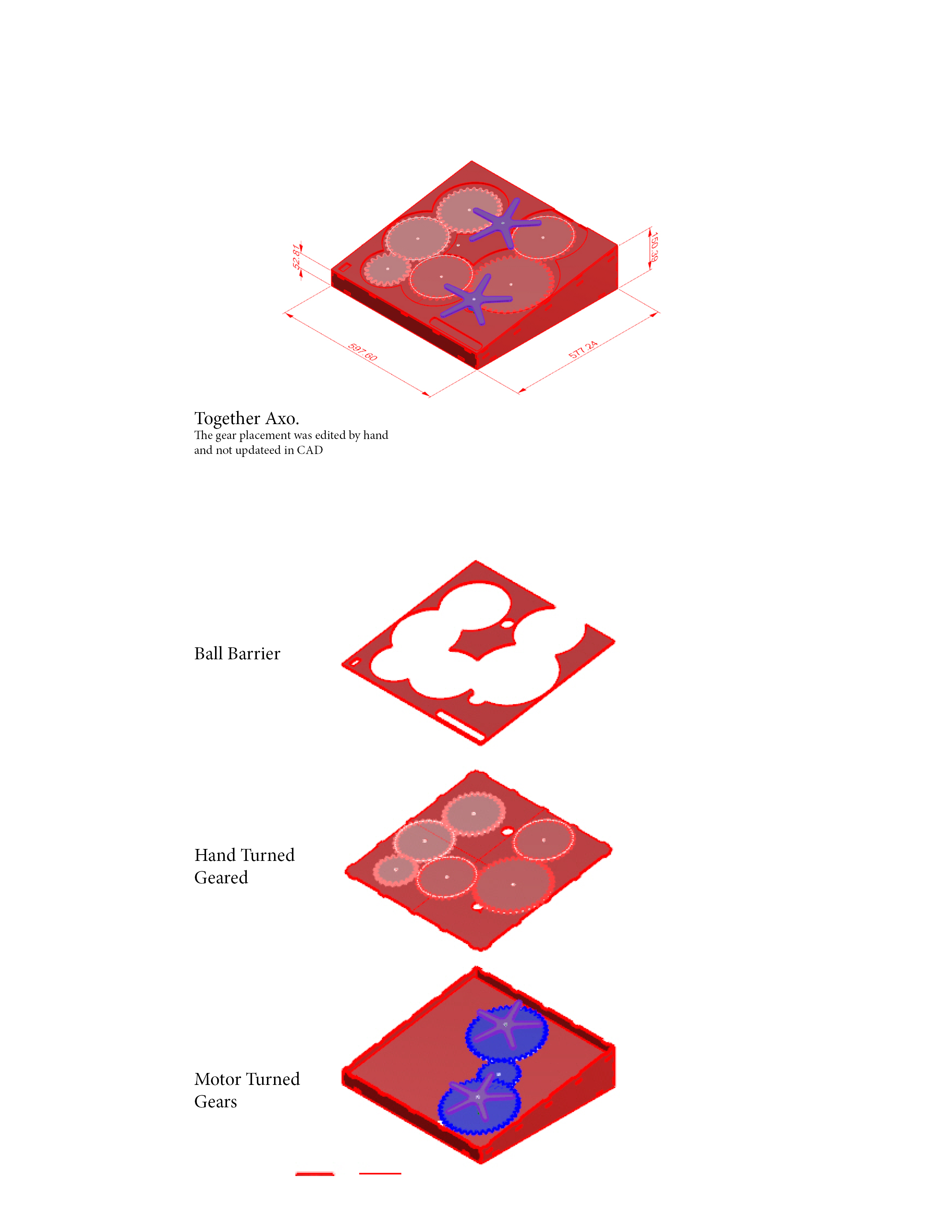
- We began the process of building the piece by creating CAD drawings in Rhino. We modeled the system and then proceeded to laser cut the pieces from plywood. Often, the addition of a new part or a design change would result in us cutting new pieces or modifying the current pieces. The incorporation of the stepper motor and sensors happened in tandem with the fabrication of the piece. It was necessary to plan for, and install them as it was being built. The code to run the arduino program happened separately, though at the same time.
Discuss your design choices.
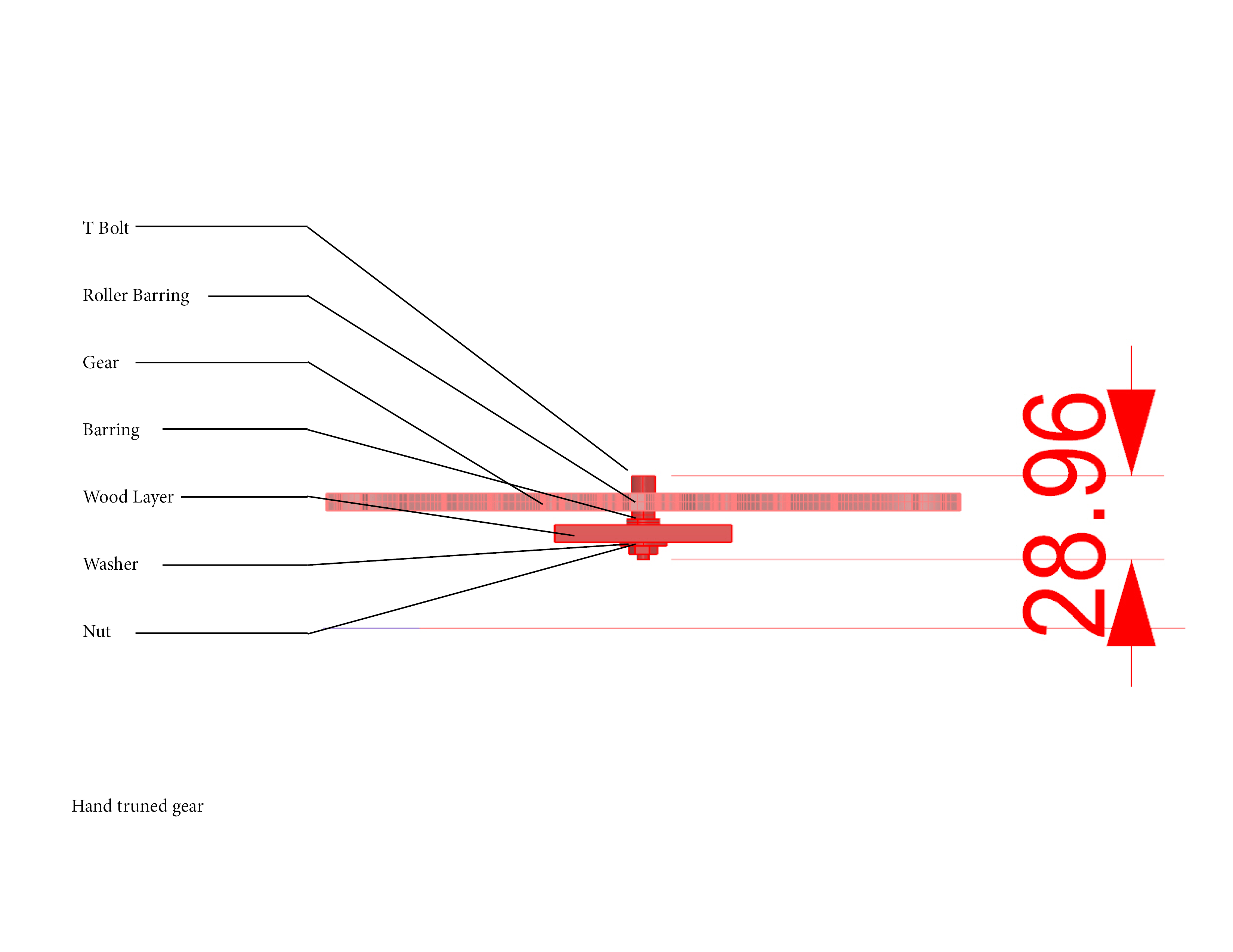
We choose to build our piece entirely out of wood to give it the effect of a hand-made toy. Of course, the hardware and LEDs were not made of wood, but the entire structure was. We had two layers of gears: a bottom, hand-spun layer and a top, motor-driven layer. The intention was to design a piece that had the ability to respond to interaction without it being intrusive. The piece was modeled in Rhino and assembled by hand.
Outcomes
- The final iteration of the piece succeeded in attracting many children and preserving their attention. This success in measured partly in comparison to the first demonstration at the museum and partly in relation to our own expectations. On average, children spent between one and two minutes with the piece. As expected, the younger kids were more interested in the physical aspects of the piece: puzzle pieces and gear. The older children, who ended up staying significantly longer, took pleasure in the sophistication and challenge the piece provided.
- The insecure connections between wires posed a problem at the museum. The wires, specifically those for the photointerrupters and LEDs would fall out of place, causing them to stop working of turn off.
- Our goal to increase the number of people interacting with our piece as well as the length of interaction succeeded on our second visit. Visitors were drawn to our piece as a result of the constant movement of the interchangeable pieces and the incorporation if LEDs. The use the interchangeable puzzle pieces helped to increase interaction, among both younger and older children. However, the way different aged children used the pieces was different. Older children were using them strategically, often swapping out pieces to further their goal in completing the maze. Younger children were more interested in the tactility of the pieces. We observed them being stacked and waved around. We noticed similar interactions in the first visit to the museum, which influenced our decision to provide more of the pieces.
Successes:
- The piece successfully kept children engaged (an average of 1 minute)
- The piece worked properly, both physically and in the code (though faulty wiring led to some issues)
- The piece was child-durable and lasted the duration of the exhibition
- The LEDs and constant movement succeeded in attracting children over to the piece
- The older children did find the piece to be “tricky,” often spending significantly more time with the piece than the younger children
Failures:
- The wiring was not secure and parts came undone during transport
- The photointerrupters were unreliable
- The code for tracking “sweeps” was did not prove to be robust
- The hand-spun gears were underneath the large motor-driven gears, which proved to be an unintuitive design flaw
Contribution
We worked closely with one another to accomplish the outcome of the piece. Annabelle’s knowledge of Rhino was highly valuable and she took on the responsibility of creating CAD drawing. Zachary was more responsible for the hardware and software aspects of the piece. All other contributions, including assembly, testing, documentation, were split more-or-less equally.
Please provide a clear statement of each author’s individual contribution to the outcomes.
Both of us contributed to the design and implementation of the project. Annabelle was individually responsible for creating the CAD files. Zachary was responsible for using those files to make the laser-cut parts. We were each engaged with the assembly. Zachary was responsible for programming the motor, LEDs, and sensors. Throughout the process, we worked closely and mostly in tandem.
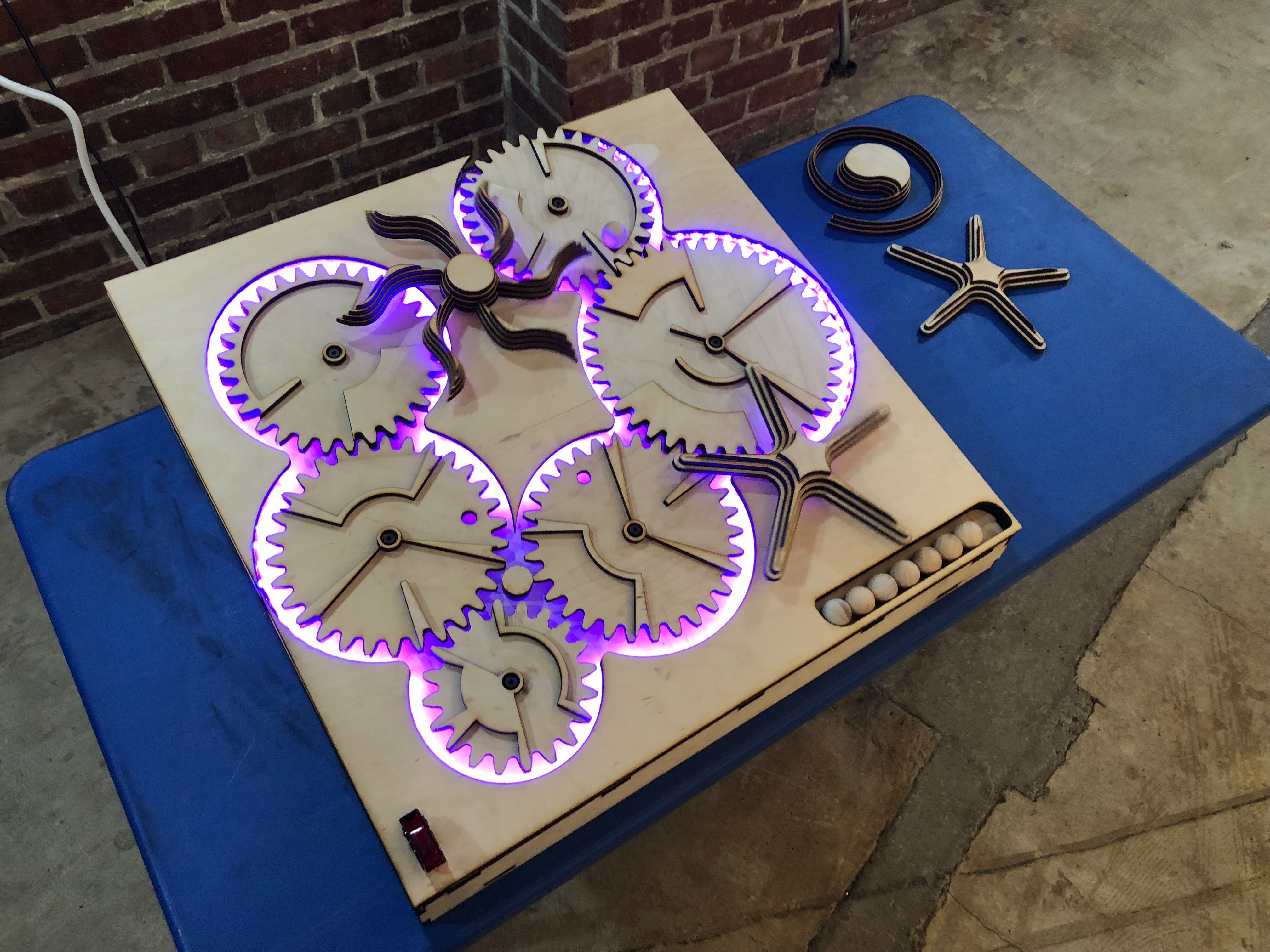
Moving pieces, interchangeable parts, LEDs, and gears were inviting for visitors.
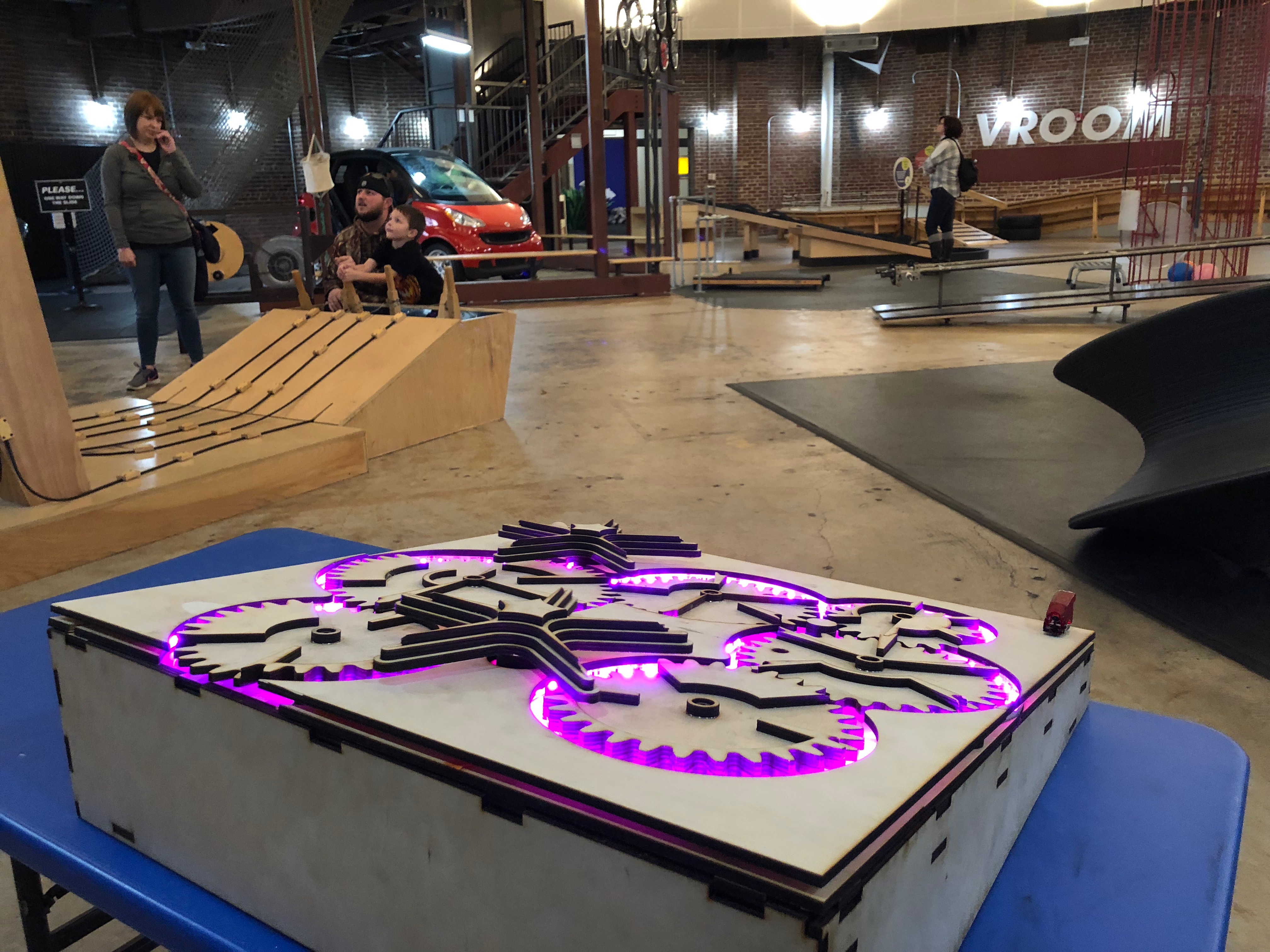
The piece was situated in the Garage of the Children’s Museum.
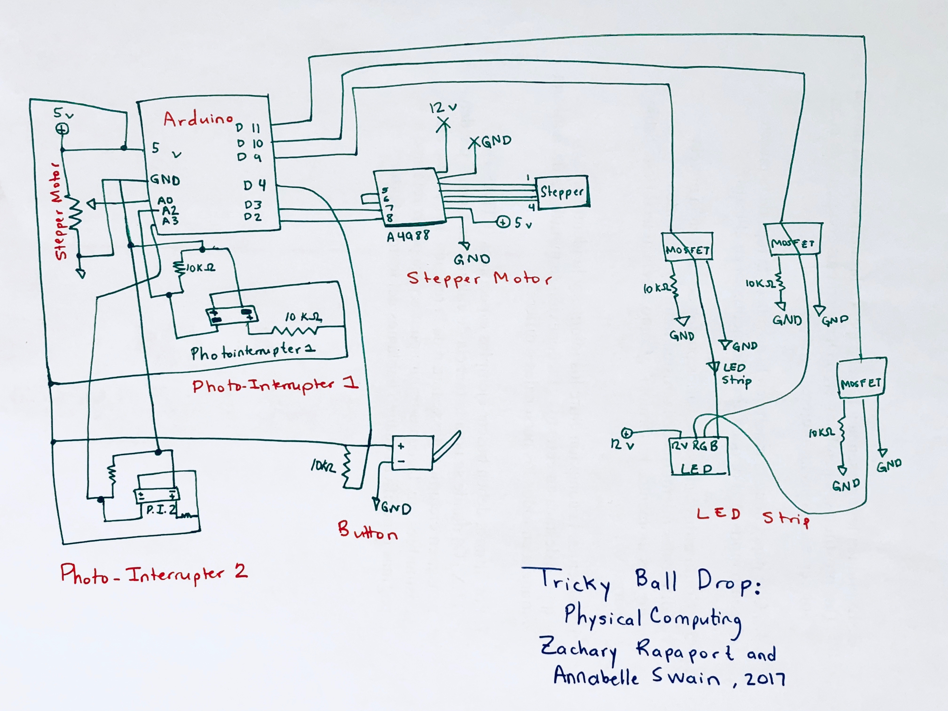
Schematic
Code:
</pre>
// Copyright (c) 2016, Garth Zeglin. All rights reserved. Licensed under the
// terms of the BSD 3-clause license as included in LICENSE.
// MOTOR: https://courses.ideate.cmu.edu/16-223/f2017/text/ex/Arduino/stepper-motor/stepper-motor.html#exercise-stepper-motor
// PHOTO INT: http://www.martyncurrey.com/connecting-an-photo-interrupter-to-an-arduino/
// LIGHTS: code: https://learn.adafruit.com/rgb-led-strips/example-code
// set up: http://www.makeuseof.com/tag/connect-led-light-strips-arduino/
//================================================================================

// STEPPER MOTOR
#define DIR_PIN 2 // The direction pin controls the direction of stepper motor rotation.
#define STEP_PIN 3 // Each pulse on the STEP pin moves the stepper motor one angular unit.

// PHOTO INTERRUPTER
int ruptPin1 = 2; // select the input pin for the interrupter
int ruptPin2 = 3; // select the input pin for the interrupter
int PI_val1 = 0; // variable to store the value coming from the sensor
int PI_val2 = 0; // variable to store the value coming from the sensor
int sweeps = 0; // number of rotations the gear has made
int high_val = 25;
int low_val = 15;
int prev_state = 0; // alternates between low (0) and high (1)

//LEDS
#define redPin 11
#define greenPin 10
#define bluePin 9

#define FADESPEED 5 // make this higher to slow down

//Button
int inPinButton = 4; // the number of the input pin
int reading;

// ================================================================================

void setup(void)
{
// Initialize the stepper driver control pins to output drive mode.
pinMode(DIR_PIN, OUTPUT);
pinMode(STEP_PIN, OUTPUT);

// Initialize the serial UART at 9600 bits per second.
Serial.begin(9600);

//LEDS
pinMode(redPin, OUTPUT);
pinMode(greenPin, OUTPUT);
pinMode(bluePin, OUTPUT);

//Button
pinMode(inPinButton, INPUT);
}
/****************************************************************/
void rotate_stepper(int steps, float speed)
{
// Configure the direction pin on the stepper motor driver based on the sign
// of the displacement.
int dir = (steps > 0)? HIGH:LOW;
digitalWrite(DIR_PIN, dir);

// Find the positive number of steps pulses to emit.
int pulses = abs(steps);

// Compute a delay time in microseconds controlling the duration of each half
// of the step cycle.
// microseconds/half-step = (1000000 microseconds/second) * (1 step/2 half-steps) / (steps/second)
unsigned long wait_time = 500000/speed;

// The delayMicroseconds() function cannot wait more than 16.383ms, so the
// total delay is separated into millisecond and microsecond components. This
// increases the range of speeds this function can handle.
unsigned int msec = wait_time / 1000;
unsigned int usec = wait_time - (1000*msec);

// Loop for the given number of step cycles. The driver will change outputs
// on the rising edge of the step signal so short pulses would work fine, but
// this produces a square wave for easier visualization on a scope.
for(int i = 0; i < pulses; i++) {
digitalWrite(STEP_PIN, HIGH);
if (msec > 0) delay(msec);
if (usec > 0) delayMicroseconds(usec);

digitalWrite(STEP_PIN, LOW);
if (msec > 0) delay(msec);
if (usec > 0) delayMicroseconds(usec);
}
}

//https://learn.adafruit.com/adafruit-arduino-lesson-3-rgb-leds/arduino-sketch
void setColor(int red, int green, int blue)
{
#ifdef COMMON_ANODE
red = 255 - red;
green = 255 - green;
blue = 255 - blue;
#endif
analogWrite(redPin, red);
analogWrite(greenPin, green);
analogWrite(bluePin, blue);
}

// ================================================================================
// Run one iteration of the main event loop. The Arduino system will call this
// function over and over forever.
void loop(void)
{

//PI
PI_val1 = analogRead(ruptPin1); // read the value from the sensor 1
PI_val2 = analogRead(ruptPin2); // read the value from the sensor 2

Serial.println(reading);

//Button
reading = digitalRead(inPinButton);

if (prev_state == 0) { //Low Value
if ((PI_val1 == high_val) or (PI_val2 > high_val)) {
prev_state = 1;
sweeps = (sweeps + 1);
delay(500);
}
}

else { //High Value
if ((PI_val1 == low_val) or (PI_val2 < low_val)) {
prev_state = 0;
sweeps = (sweeps + 1);
}
}

{
if (sweeps == 0) {
setColor(0, 255, 0); // green
}
if (sweeps == 1) {
setColor(50, 255, 0);
}
if (sweeps == 2) {
setColor(100, 255, 0);
}
if (sweeps == 3) {
setColor(150, 255, 0);
}
if (sweeps == 4) {
setColor(200, 255, 0);
}
if (sweeps == 5) {
setColor(255, 255, 0); // yellow
}
if (sweeps == 6) {
setColor(255, 200, 0);
}
if (sweeps == 7) {
setColor(255, 150, 0);
}
if (sweeps == 8) {
setColor(255, 100, 0);
}
if (sweeps == 9) {
setColor(255, 60, 0);
}
if (sweeps == 10) {
setColor(255, 30, 0);
}
if (sweeps == 11) {
setColor(255, 0, 0); // red
}
}

if (reading == 1) {

if (sweeps == 0) {
rotate_stepper( -1, 20.0);
}
if (sweeps == 1) {
rotate_stepper( -1, 25.0);
}
if (sweeps == 2) {
rotate_stepper( -1, 25.0);
}
if (sweeps == 3) {
rotate_stepper( -1, 35.0);
}
if (sweeps == 4) {
rotate_stepper( -1, 35.0);
}
if (sweeps == 5) {
rotate_stepper( -1, 45.0);
}
if (sweeps == 6) {
rotate_stepper( -1, 45.0);
}
if (sweeps == 7) {
rotate_stepper( -1, 55.0);
}
if (sweeps == 8) {
rotate_stepper( -1, 55.0);
}
if (sweeps == 9) {
rotate_stepper( -1, 65.0);
}
if (sweeps == 10) {
rotate_stepper( -1, 65.0);
sweeps = 0;
}
}}
Leave a Reply
You must be logged in to post a comment.