Narrative Description:
The name is tilting maze. This device let children control the motion of a table to move in different directions and solve a maze. The children will be surprised to see that the table can follow their motion to rotate and they will be dedicated to moving the ball to the destination. It is preferred to be installed at the playground where the parachute is.
Ideally, a kid will come across the table and try to move the ball to the end by hand, but then he sees the direction printed on the side that he should try to use a tool to move the table and directly touch the ball will not count as a win. So he picked up the tool and play with it, and when he moves his hand, he will see the table move as his hands move. He may play with it for some time to realize that the tool is used for move the table to move the ball and solve the maze. Then he will probably spend 5 minutes moving the table and when the ball reaches its destination, the device will congratulate the kids and he will be happy. The hallmark of successful will be the shining of many LEDs around the table. I expect the kids to be thrilled by this effect and leave happily.
Technical Outline:
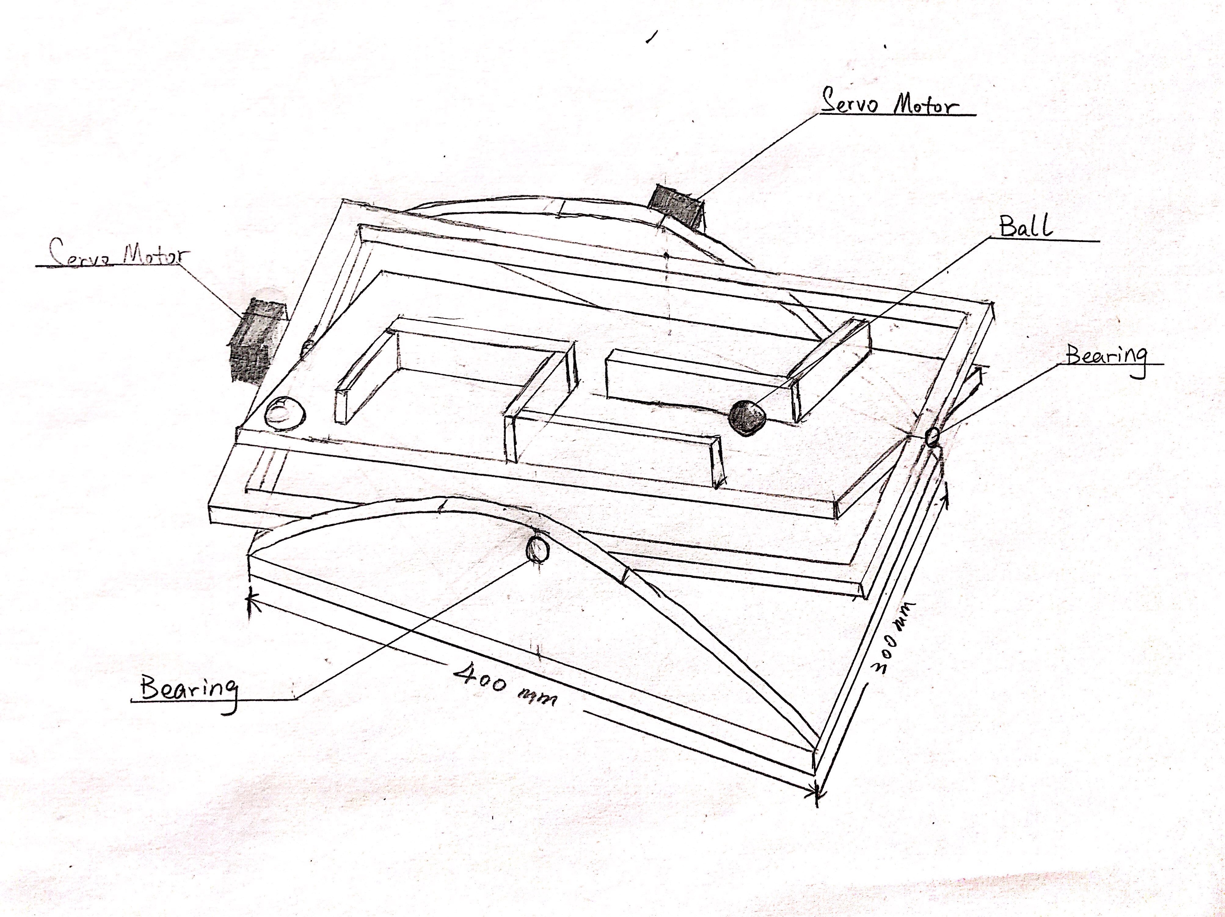
- The tilting table has motions in two degrees of freedom: roll and pitch. We will use two servo motors to achieve these two independent motions.
- The table should follow the guidance from the user. Thus we will need an interface that could let the user command the table’s pose with relatively intuitive methods. We propose to use an IMU to measure the desired table orientation. We will also need to design a user-friendly, hand-held input device as a user interface.
- Both the main structure of the tilting table and the maze on the table will be made out of wood and manufactured using laser-cutting. The user interface will be 3D-printed to the desired shape, making it easy to understand and use.
- One of the main technical challenges is converting the sensor input to the actual pose of the table. This involves filtering of the sensor reading and also the inverse kinematics of translating the desired pose to the servo motor angles. Another technical challenge would be designing a user-friendly interface, which is intuitive for children and robust under misuses.
Budget Outline & Timeline:
Please refer to the BOM tab in our project schedule.
Project Management:
Proof-of-concept:
- We need to test the IMU to ensure that the one we bought can provide relatively accurate measurement.
- We need to test if the combination of two servos can provide two degrees of freedom.
First on-site test:
- We need to test if the sensor is working fine in places where people are working around.
- We need to test if the setup is easy.
Known unknowns:
- Currently, we don’t know if we need another kind of sensor to help validate IMU feedback in a place with alot of people but we will know when we finish the on-site test.
- We don’t know what is the limit speed and angle of two servos if there is a kid moving the IMU very fast.
Sketches:
Isometric sketch:
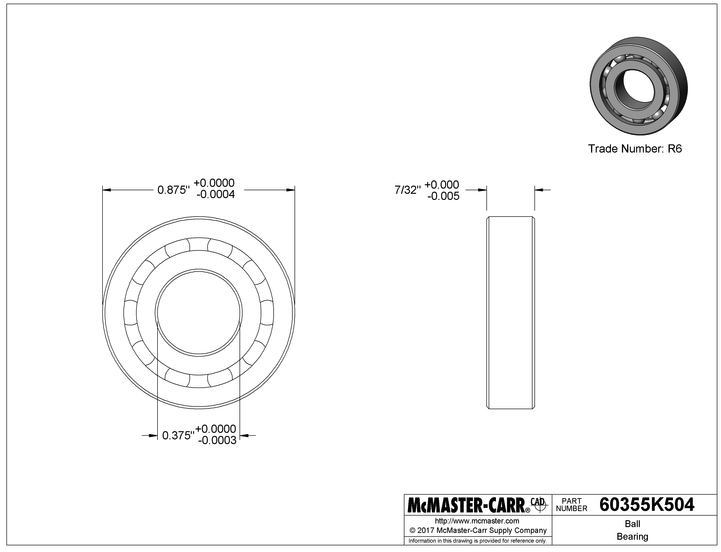
Bearings:
Shafts:

Leave a Reply
You must be logged in to post a comment.