Day 4: (Mon Sep 9) Basic Electronics
Notes for 2019-09-09. See also the Fall 2019 Calendar.
Notes from Day 3
I apologize for not getting to the laser-cutting discussion last time, hopefully my notes on DXF export helped and the staff covered the rest.
Agenda
Administrative
Is anyone still not qualified on the laser cutters?
Please note cubbies for storage.
Assignments
Due today: Demo 1: Rocking and Rolling
Due Mon Sep 16: Demo 2: Single-bit Feedback
Note: I may bounce some blog entries back to you for reformatting: no penalty this time, I just want to create a readable site.
In-class
Quick check-off demos. Please show your project to your tablemates while I am coming around.
Discussion of basic electronics theory.
Demos of lab equipment: DMM, oscilloscope.
Hand out the kit box and more of the components. See Course Kit for inventory.
Try out Exercise: Continuity Tests.
Try out Exercise: Read Switch Input.
Figures


Essential Theory
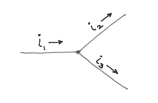
Kirchhoff’s current law (KCL).
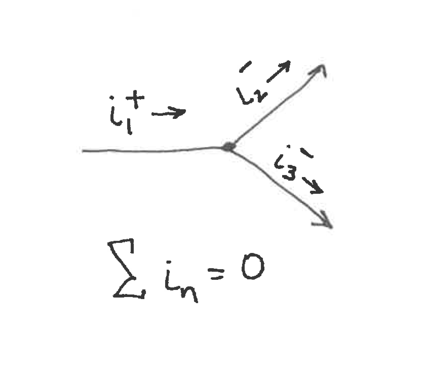
Kirchhoff’s current law (KCL).
Kirchhoff’s voltage law (KVL).
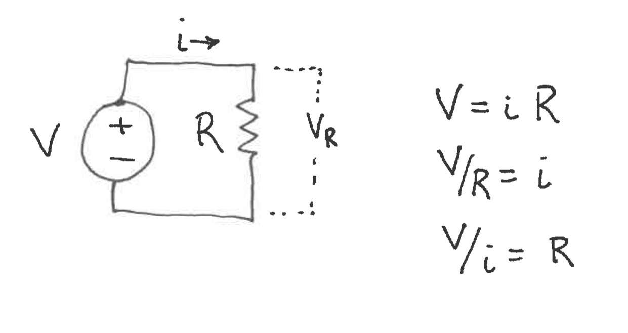
Ohm’s Law.
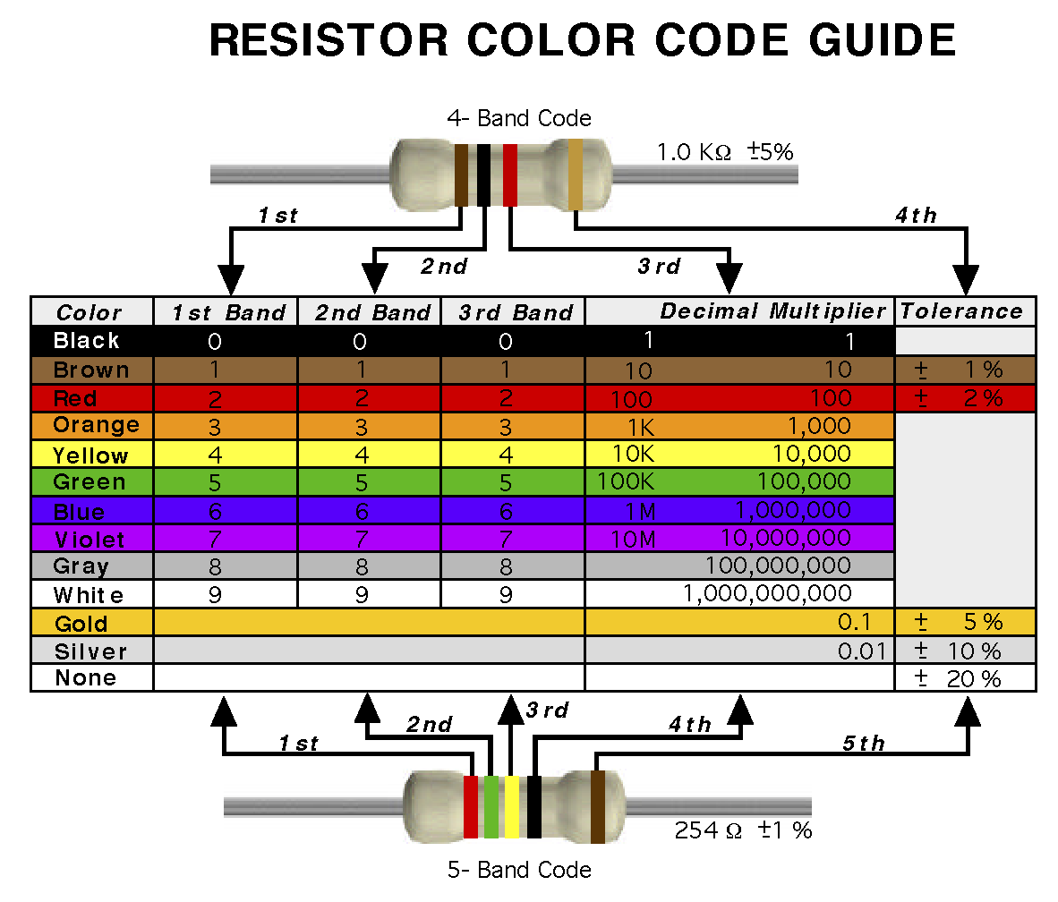
We use 1/4-Watt resistors with axial leads. The part value is indicated by the colored bands.

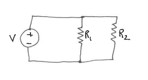
A voltage divider, the essential topology for most of our circuits. For more detail, please see Exercise: Voltage Divider Review.
Essential Circuits

A switch with a pullup resistor, analyzable as a voltage divider.


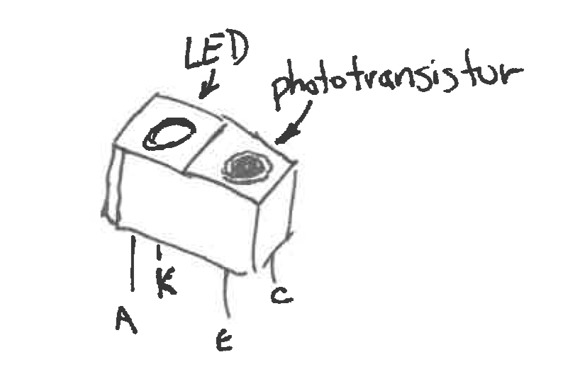

A photointerruptor circuit includes a current-limiting resistor for the LED and a bias resistor for the phototransistor.
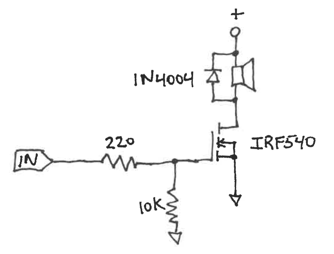
A single-channel unidirectional power driver using a IRF540 MOSFET. For more detail, please see Exercise: Unipolar Drivers.
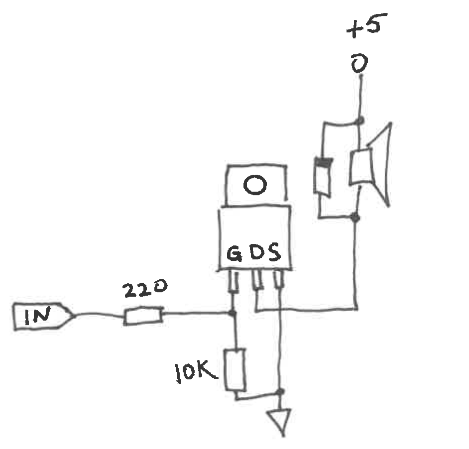
A more graphical representation of the IRF540 MOSFET circuit.
Essential Lab Equipment
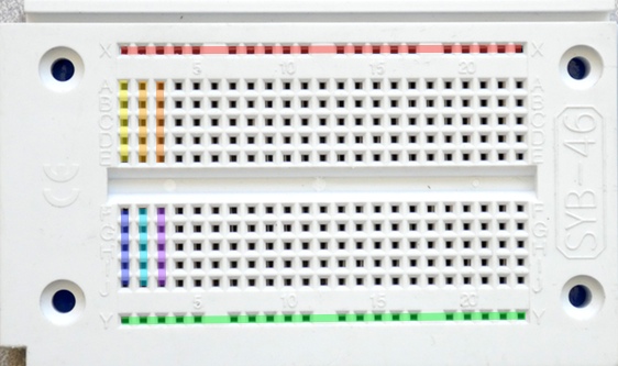
Solderless breadboards are our workhorse for electronics prototyping. Each short row of five holes connects together by an internal metal clip and forms a single circcuit node. Each long bus row is a node. Please disregard the +/- bus labels on your breadboards.
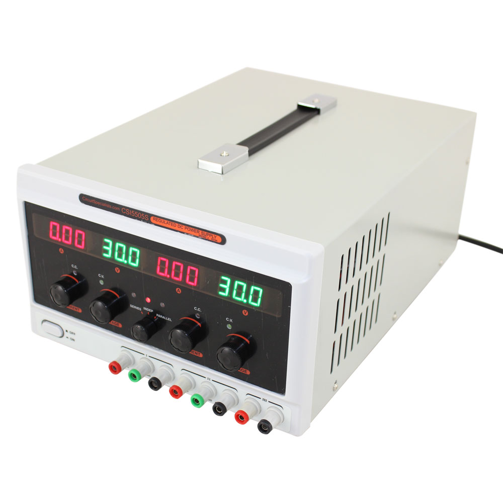
Three-channel lab power supplies.

Digital multi-meter (DMM).

Digital oscilloscope. For more details, please see Oscilloscope Guide.