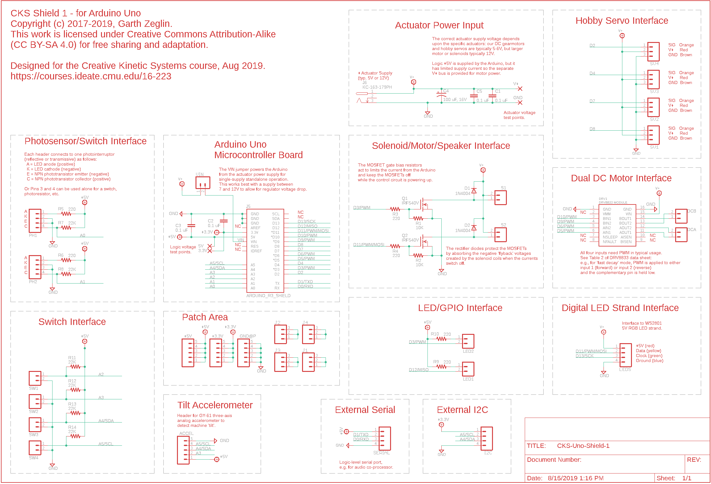
CKS-1 Arduino Uno Shield
Physical computing projects involve many individual sensors and actuators connected to the logic with a lot of wiring. This is a vulnerable point for building a machine which is engaged physically by the users. In an effort to simplify the wiring problem, the course provides a ‘shield’ board which interfaces the Arduino microcontroller to a useful set of interface hardware and connectors for driving a physical machine.
Rev A Layout
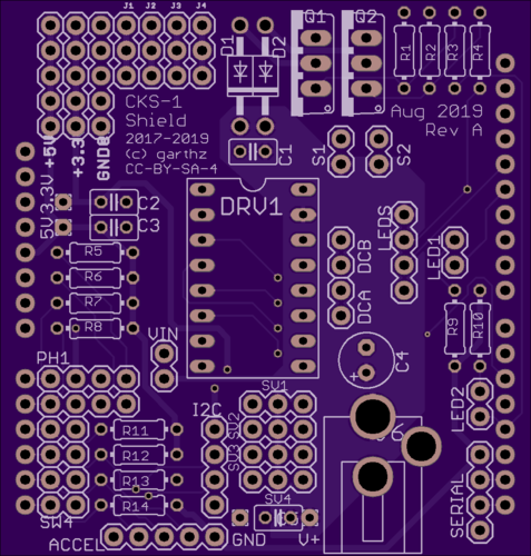
Rendered images including copper, silkscreen, and mask: top view on left, bottom view on right.
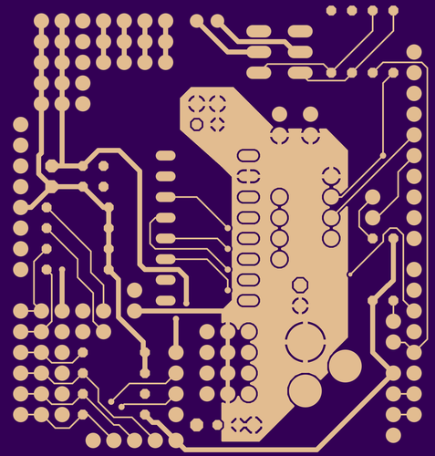
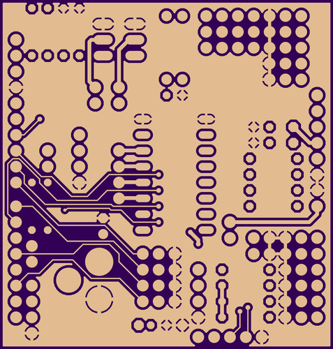
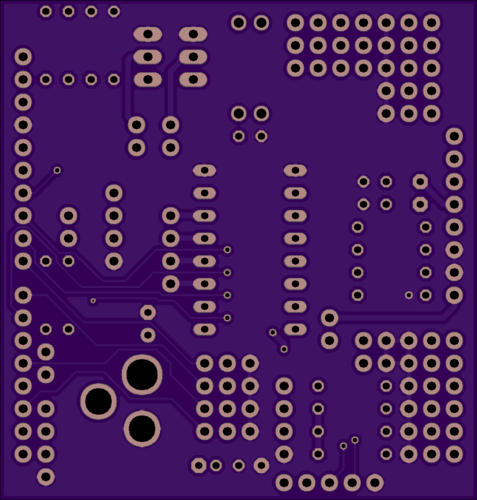
Rendered images of copper layers only: top view on left, bottom view on right.
CKS-Uno-Shield-1-RevA.brdCKS-Uno-Shield-1-RevA.schPin Assignment Notes
The following table describes the default usage mode for each Arduino pin and two suggested alternate uses for some. Additional configurations are possible.
pin name |
use |
alt1 |
alt2 |
primary function |
alternate function |
second alternate function |
|---|---|---|---|---|---|---|
D0 |
RX |
RX |
GPIO |
USB serial |
external TTL serial |
GPIO via SERIAL connector |
D1 |
TX |
TX |
GPIO |
USB serial |
external TTL serial |
GPIO via SERIAL connector |
D2 |
GPIO |
Servo4 |
GPIO |
|||
D3 |
PWM |
GPIO |
MOSFET1 |
LED2 GPIO |
||
D4 |
GPIO |
Servo3 |
GPIO |
|||
D5 |
PWM |
GPIO |
DRV8833 |
|||
D6 |
PWM |
GPIO |
DRV8833 |
|||
D7 |
GPIO |
Servo2 |
GPIO |
|||
D8 |
GPIO |
Servo1 |
GPIO |
|||
D9 |
PWM |
GPIO |
DRV8833 |
|||
D10 |
PWM |
GPIO |
DRV8833 |
|||
D11 |
PWM |
MOSI |
GPIO |
MOSFET2 |
WS2801 LEDS |
GPIO via LEDS connector |
D12 |
GPIO |
MISO |
LED1 GPIO |
|||
D13 |
LED |
SCK |
GPIO |
onboard LED |
WS2801 LEDS |
GPIO via LEDS connector |
A0 |
ADC0 |
GPIO |
photosensor/switch |
GPIO |
||
A1 |
ADC1 |
GPIO |
photosensor/switch |
GPIO |
||
A2 |
ADC2 |
GPIO |
switch |
GPIO |
||
A3 |
ADC3 |
ADC3 |
switch |
ADXL335 connector |
||
A4 |
ADC4 |
ADC4 |
SDA |
switch |
ADXL335 connector |
I2C connector |
A5 |
ADC5 |
ADC5 |
SCL |
switch |
ADXL335 connector |
I2C connector |
Parts Lists and Assembly Notes
The shield is designed to support many alternative configurations, so the parts are organized by functional unit. The first set includes the standard set of components essential for any use, listed in a recommended assembly order.
The parts labeled ‘Course Kit’ were given to you with the breadboarding kit; ‘PhysComp Stock’ can be taken from the lab shelves; the parts labeled ‘Mouser’ have been purchased and will be handed out with the shield boards.
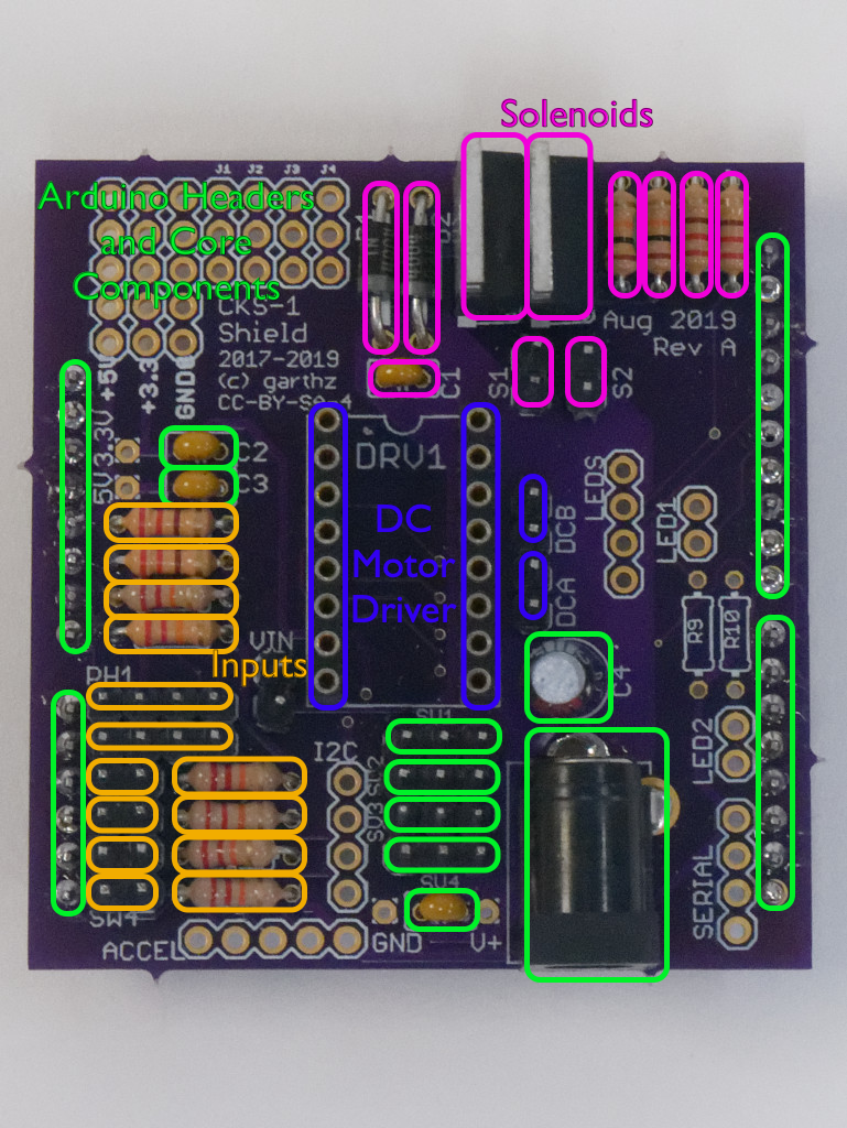
Visual Section Guide
The following assembly guide is divided into sections. The colors indicate components for the four main sections: Arduino Headers and Core Components in green, Inputs in orange, DC Motor Driver in blue, Solenoids in magenta.
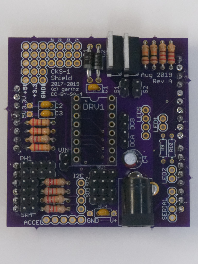
Photographs of a partly assembled shield can be found in CKS-1 Arduino Uno Shield Gallery.
Arduino Headers and Core Components
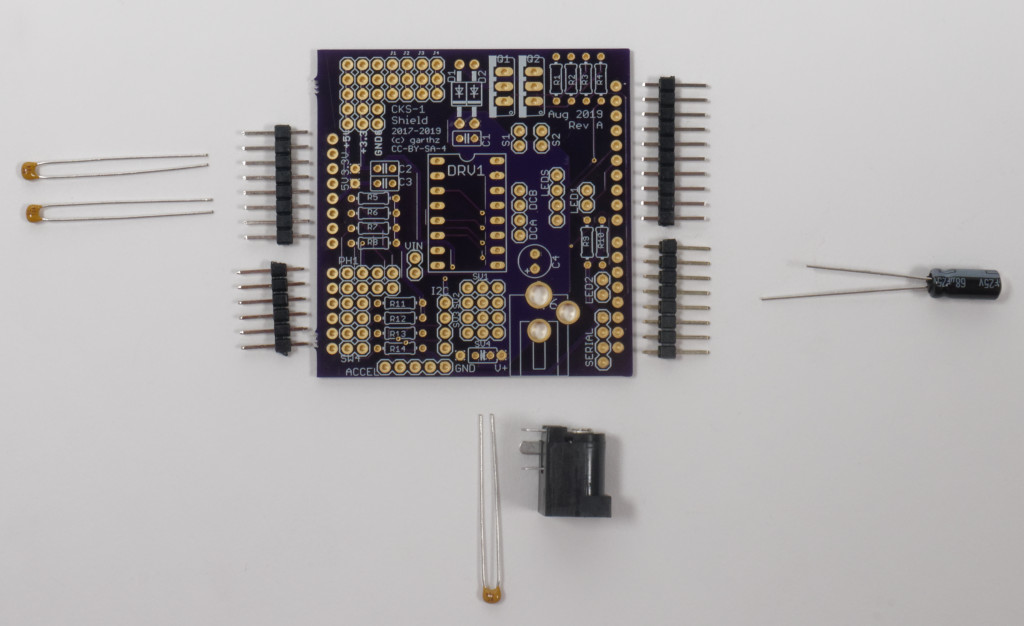
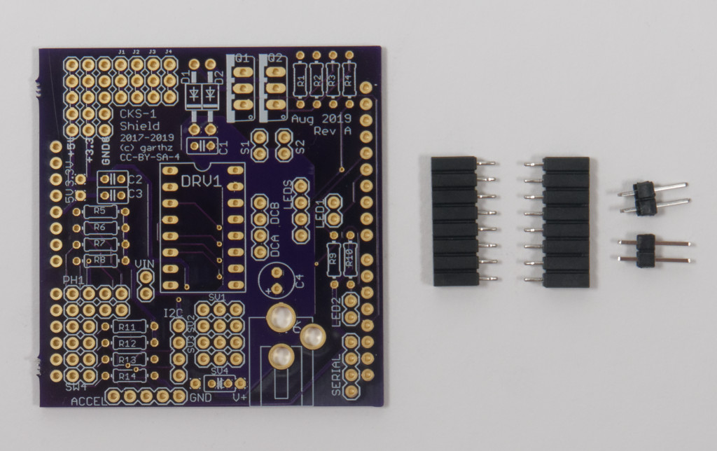
Shield board with Arduino header strips, capacitors, and barrel plug. (Servo headers not shown.)
A good first step is to install the strip headers which connect the shield board to the Arduino. Note that these install on the bottom, they are the only components to do so. The strip headers come in long rows but can be carefully trimmed to the right number of pins using diagonal cutters. The recommended strategy is to pre-cut the headers and pre-assemble them onto the Arduino headers and board prior to any soldering. This will ensure the headers are aligned and correctly seated. The headers can then be soldered in place, then the shield disassembled from the Arduino.
The core component set also includes the barrel plug connector for motor power input, decoupling capacitors for filtering the power, and male connector pins for attaching hobby servos.
Part Label |
Description |
Source |
Part Identifier |
Manufacturer |
Part Number |
Notes |
|---|---|---|---|---|---|---|
J5 |
Arduino Uno |
Course Kit |
Elegoo |
EL-CB-001 |
Use Arduino for alignment while soldering J5 headers, then remove until done. |
|
J5 |
male header, single row, 10 pin, on bottom, D8-D13 etc. |
PhysComp Stock |
Part 0742, Bin B2-R6-C1 |
Note: part solders on bottom of board! It mates with the Uno below. |
||
J5 |
male header, single row, 6 pin, on bottom, analog section |
PhysComp Stock |
Part 0742, Bin B2-R6-C1 |
Ibid. |
||
J5 |
male header, single row, 8 pin, on bottom, D0-D7 |
PhysComp Stock |
Part 0742, Bin B2-R6-C1 |
Ibid. |
||
J5 |
male header, single row, 8 pin, on bottom, power section |
PhysComp Stock |
Part 0742, Bin B2-R6-C1 |
Ibid. |
||
J6 |
PC mount barrel plug adapter, Kobiconn 163-179PH |
Mouser |
163-179PH-EX |
Kobiconn |
163-179PH-EX |
|
C2 |
0.1 uF, ceramic capactor, radial 0.1” leads |
Mouser |
594-K104M15X7RF53L2 |
Vishay |
K104M15X7RF53L2 |
|
C3 |
0.1 uF, ceramic capactor, radial 0.1” leads |
Mouser |
594-K104M15X7RF53L2 |
Vishay |
K104M15X7RF53L2 |
|
C5 |
0.1 uF, ceramic capactor, radial 0.1” leads |
Mouser |
594-K104M15X7RF53L2 |
Vishay |
K104M15X7RF53L2 |
|
C4 |
68 uF, 25V, electrolytic capacitor, radial, 0.1” leads, 5mm OD |
Mouser |
667-EEU-HD1E680 |
Panasonic |
EEU-HD1E680 |
Orient according to silkscreen. |
SV1 |
male header, single row, 3 pin |
PhysComp Stock |
Part 0742, Bin B2-R6-C1 |
|||
SV2 |
male header, single row, 3 pin |
PhysComp Stock |
Part 0742, Bin B2-R6-C1 |
|||
SV3 |
male header, single row, 3 pin |
PhysComp Stock |
Part 0742, Bin B2-R6-C1 |
|||
SV4 |
male header, single row, 3 pin |
PhysComp Stock |
Part 0742, Bin B2-R6-C1 |
|||
Inputs
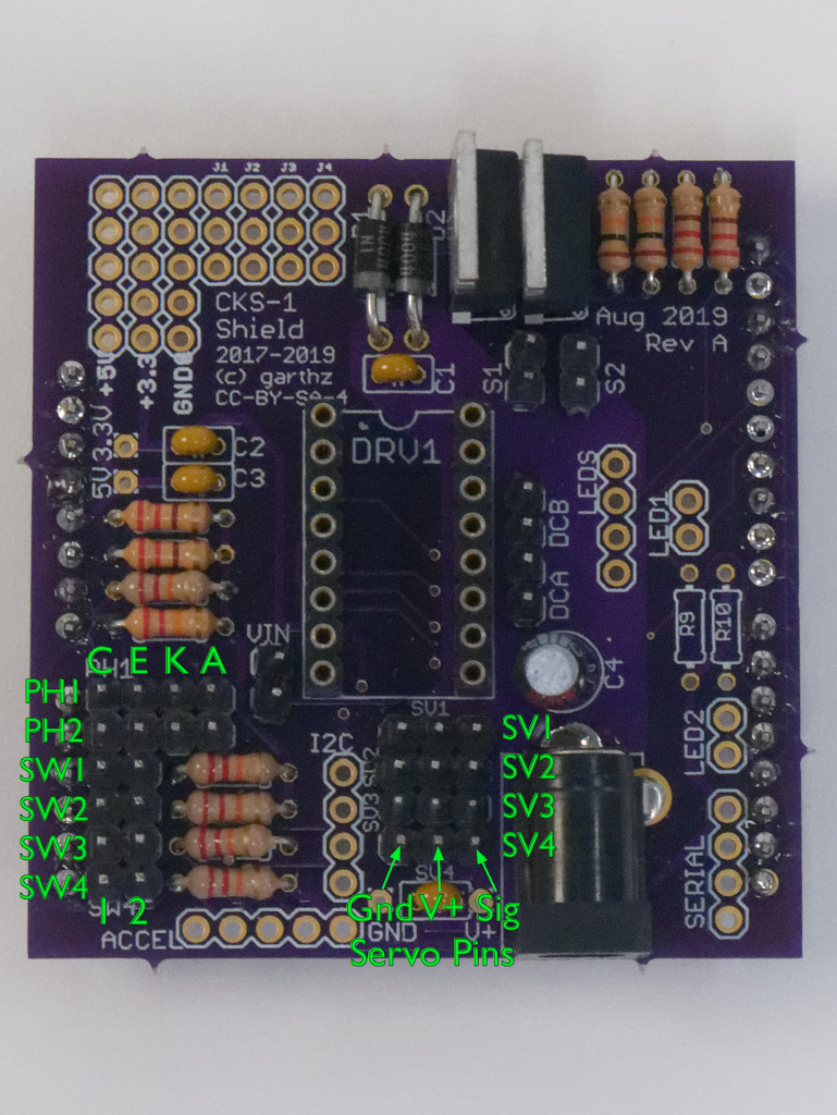
Partial pinout diagram highlighting the layout of the input and servo connectors. Note that the input headers each have the Arduino input adjacent to the Arduino headers at the board edge: the C/4 pin for the photosensors, and pin 1 for the switch inputs.
The six input channels can be separately assembled as needed. Soldering the parts will require removing the shield from the Arduino.
Part Label |
Description |
Source |
Part Identifier |
Manufacturer |
Part Number |
Notes |
|---|---|---|---|---|---|---|
R5 |
220 ohm resistor, axial, 0.25 watt |
PhysComp Stock |
Part 0017, Bin B8-R2-C1 |
|||
R6 |
220 ohm resistor, axial, 0.25 watt |
PhysComp Stock |
Part 0017, Bin B8-R2-C1 |
|||
R7 |
22K resistor, axial, 0.25 watt |
PhysComp Stock |
Part 0049, Bin B8-R4-C1 |
|||
R8 |
22K resistor, axial, 0.25 watt |
PhysComp Stock |
Part 0049, Bin B8-R4-C1 |
|||
R11 |
22K resistor, axial, 0.25 watt |
PhysComp Stock |
Part 0049, Bin B8-R4-C1 |
|||
R12 |
22K resistor, axial, 0.25 watt |
PhysComp Stock |
Part 0049, Bin B8-R4-C1 |
|||
R13 |
22K resistor, axial, 0.25 watt |
PhysComp Stock |
Part 0049, Bin B8-R4-C1 |
|||
R14 |
22K resistor, axial, 0.25 watt |
PhysComp Stock |
Part 0049, Bin B8-R4-C1 |
|||
SW1 |
male header, single row, 2 pin |
PhysComp Stock |
Part 0742, Bin B2-R6-C1 |
|||
SW2 |
male header, single row, 2 pin |
PhysComp Stock |
Part 0742, Bin B2-R6-C1 |
|||
SW3 |
male header, single row, 2 pin |
PhysComp Stock |
Part 0742, Bin B2-R6-C1 |
|||
SW4 |
male header, single row, 2 pin |
PhysComp Stock |
Part 0742, Bin B2-R6-C1 |
|||
PH1 |
male header, single row, 4 pin |
PhysComp Stock |
Part 0742, Bin B2-R6-C1 |
|||
PH2 |
male header, single row, 4 pin |
PhysComp Stock |
Part 0742, Bin B2-R6-C1 |
|||
DC Motors
Shield board with female headers for the DRV8833 and male headers for the motor pins.
A pair of DC motors can be driven from the DRV8833. Please note the use of female headers to provide a socket for the module. The motor pins are male.
Part Label |
Description |
Source |
Part Identifier |
Manufacturer |
Part Number |
Notes |
|---|---|---|---|---|---|---|
DRV1 |
female header, single row, 8 pin |
Mouser |
437-8018700810143101 |
Preci-dip |
801-87-008-10-143101 |
|
DRV1 |
female header, single row, 8 pin |
Mouser |
437-8018700810143101 |
Preci-dip |
801-87-008-10-143101 |
|
DCA |
male header, single row, 2 pin |
PhysComp Stock |
Part 0742, Bin B2-R6-C1 |
|||
DCB |
male header, single row, 2 pin |
PhysComp Stock |
Part 0742, Bin B2-R6-C1 |
|||
DRV1 |
DRV8833 Module |
Course Kit |
Pololu |
2130 |
Solenoid/Speaker/Relay Drivers
Various unidirectional devices can be driven from the MOSFET circuits. Each is independent and could be separately assembled if desired. Note the polarity of the diodes and MOSFETS, please match the annotations in the silkscreen.
Part Label |
Description |
Source |
Part Identifier |
Manufacturer |
Part Number |
Notes |
|---|---|---|---|---|---|---|
D1 |
1N4004, rectifier diode, DO41 axial package |
PhysComp Stock |
Part 4004, Bin B8-R7-C1 |
Orient according to silkscreen. |
||
D2 |
1N4004, rectifier diode, DO41 axial package |
PhysComp Stock |
Part 4004, Bin B8-R7-C1 |
Orient according to silkscreen. |
||
C1 |
0.1 uF, ceramic capactor, radial 0.1” leads |
Mouser |
594-K104M15X7RF53L2 |
Vishay |
K104M15X7RF53L2 |
|
Q1 |
IRF540V, Power MOSFET, N-channel, TO-220AB package |
PhysComp Stock |
Part 0540, Bin B9-R8-C1 |
Infineon |
IRF540ZPBF |
Orient according to silkscreen. |
Q2 |
IRF540V, Power MOSFET, N-channel, TO-220AB package |
PhysComp Stock |
Part 0540, Bin B9-R8-C1 |
Infineon |
IRF540ZPBF |
Orient according to silkscreen. |
R1 |
10K resistor, axial, 0.25 watt |
PhysComp Stock |
Part 0045, Bin B8-R3-C7 |
|||
R2 |
10K resistor, axial, 0.25 watt |
PhysComp Stock |
Part 0045, Bin B8-R3-C7 |
|||
R3 |
220 ohm resistor, axial, 0.25 watt |
PhysComp Stock |
Part 0017, Bin B8-R2-C1 |
|||
R4 |
220 ohm resistor, axial, 0.25 watt |
PhysComp Stock |
Part 0017, Bin B8-R2-C1 |
|||
S1 |
male header, single row, 2 pin |
PhysComp Stock |
Part 0742, Bin B2-R6-C1 |
|||
S2 |
male header, single row, 2 pin |
PhysComp Stock |
Part 0742, Bin B2-R6-C1 |
Miscellaneous Components
The remaining components, some of which interfere with other circuits:
optional accelerometer module
“LED” pins with dropping resistors, also usable as spare digital inputs or outputs
“LEDS” connector for WS2801 LED strand or output-only SPI
“I2C” connector for I2C bus
“SERIAL” connector for UART serial
“VIN jumper for operating the Arduino off the motor power independent of USB power or the Arduino barrel plug
Part Label |
Description |
Source |
Part Identifier |
Manufacturer |
Part Number |
Notes |
|---|---|---|---|---|---|---|
ACCEL |
female header, single row, 5 pin |
PhysComp Stock |
Part 0750, Bin B2-R7-C1 |
|||
ACCEL |
GY-61 three-axis analog accelerometer module |
PhysComp Stock |
Part 0368, Bin B12-R4-C7 |
|||
R9 |
220 ohm resistor, axial, 0.25 watt |
PhysComp Stock |
Part 0017, Bin B8-R2-C1 |
|||
R10 |
220 ohm resistor, axial, 0.25 watt |
PhysComp Stock |
Part 0017, Bin B8-R2-C1 |
|||
LED1 |
male header, single row, 2 pin |
PhysComp Stock |
Part 0742, Bin B2-R6-C1 |
|||
LED2 |
male header, single row, 2 pin |
PhysComp Stock |
Part 0742, Bin B2-R6-C1 |
|||
LEDS |
male header, single row, 4 pin |
PhysComp Stock |
Part 0742, Bin B2-R6-C1 |
Typically provided for WS2801 LED strand. |
||
I2C |
male header, single row, 4 pin |
PhysComp Stock |
Part 0742, Bin B2-R6-C1 |
|||
SERIAL |
male header, single row, 4 pin |
PhysComp Stock |
Part 0742, Bin B2-R6-C1 |
|||
VIN |
male header, single row, 2 pin |
PhysComp Stock |
Part 0742, Bin B2-R6-C1 |
|||
VIN |
jumper |
PhysComp Stock |
Part 0726, Bin B2-R4-C5 |
May use this optional jumper to power Arduino from motor power. |
||
Additional Notes
J1, J2, J3, and J4 provide jumpering pads for prototyping or patching, no parts
are specified. The +5V, +3.3V, and GND@P pads can provide logic
power for prototyping or patching; these are not suitable for high power loads
like actuators or lights.
The VIN jumper directly connects the motor power into the Arduino VIN input, i.e., the shield barrel plug into the same circuit as the Arduino barrel plug. This can enable running the whole system from one supply, but using the VIN jumper requires care:
the motor supply needs to be 7-12V to account for regulator drop, else the Arduino logic supply will ‘brown out’
an inadequate motor supply will lead to logic power glitches, causing unpredictable errors and Arduino resets
it is all too easy to forget it is installed and plug a second power supply into the Arduino barrel plug, frying both supplies as they are directly connected to each other via the jumper
Additional Documentation
External Resources
Product information:
Library documentation:
Related course exercises, with sample circuits, code, and explanation:
Licensing

The CKS-1 Arduino Uno Shield design and documentation by Garth Zeglin are licensed under a Creative Commons Attribution-ShareAlike 4.0 International License. Based on a work at https://courses.ideate.cmu.edu/16-223/f2019/.