For the second demo, I decided to laser cut a new object to integrate a photointerruptor. The new object looks like a vertically flipped Omega symbol, which oscillates quite well.
For this demo, I attached the photointerruptor near the front of the base and the servo motor at the bottom of the base. The servo motor has been programmed in a way to give small jerks to the the object and thus, slowly make it move forward. The photointerruptor receives analog values through the pin A1, which is read and according to the a certain threshold value, it controls whether the servo motor stops or continues. Thus, if there is a wall or another object in front of the moving omega, it stops moving. Once there is no obstruction, the omega starts moving again. The following video demonstrates how this works.
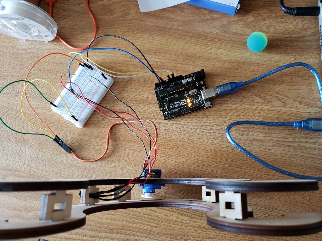
If we look closely, the photointerruptor leads have been soldered to wires that go back to connect to a breadboard, which is then connected to the Arduino to receive inputs. The following picture shows the connections and how they look on the inside.
Here is the code I used to make this demo possible:
#include <Servo.h>
Servo hi;
int sensorValue=0;
int sensorPin=A1;
void setup() {
// put your setup code here, to run once:
hi.attach(9);
Serial.begin(9600);
pinMode(sensorPin,INPUT);
}
void loop() {
// put your main code here, to run repeatedly:
sensorValue = analogRead(sensorPin);
Serial.println(sensorValue);
while (1==1){
if (sensorValue>=800){
hi.write(0);
delay(1000);
sensorValue = analogRead(sensorPin);
Serial.println(sensorValue);
hi.write(75);
delay(500);
}else{
sensorValue = analogRead(sensorPin);
Serial.println(sensorValue);
hi.write(0);
delay(500);
}
}
}
Leave a Reply
You must be logged in to post a comment.