Exercise: Resistive Circuits in Tinkercad
Electrical theory is the foundation for incorporating computing into physical systems. We will focus our theory discussion around the humble resistor, an elementary electronic component which will appear in most of our circuits.
This comprehensive exercise will walk through all the essential circuits knowledge needed for the course, using Tinkercad Circuits as an experimental platform. It is longer than some, as it assumes a full seven days are available for completion.
Using Tinkercad has advantages and disadvantages. As a simulator, it has predictable behavior which closely corresponds to theory, so it will help us focus on the abstract principles. However, as a simulator, it is also “doomed to succeed”, meaning it won’t exhibit the failings and quirks of implementing idealized circuits on real physical hardware. But you’ll have plenty of opportunity to learn to manage actual hardware once we move to physical circuit breadboarding.

Schematic symbol for a resistor.
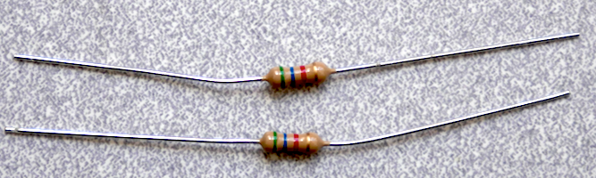
Two physical resistor components. The color bands indicate these are engineered for 5600 Ohm resistance (green-blue-red), with a 5% tolerance on the value (gold). The size and shape are clues that it is a carbon-composition resistor rated for 1/4 Watts of energy dissipation.
Objectives
After this exercise, you should be able to:
Read an electronic schematic, including basic schematic symbols and connectivity.
Construct a breadboard circuit from a schematic diagram.
Construct a switch input circuit and measure its state.
Calculate current and voltage for simple resistive circuits using Ohm’s Law, KVL, and KCL.
Construct a current-limited LED output circuit, including selection of the limiting resistor value.
Design a voltage divider bridge circuit for a photoresistor, including selection of the bias resistor value.
Construct a photoresistor bridge circuit and measure simulated light levels.
Reference Guides
Please review the following reference guides as needed:
Assigned video lecture clips, including specific commentary on this exercise.
Steps and observations
The following checklist will walk you step by step through building a collection of circuits to submit within a single Tinkercad sketch. Please go through all the steps; the point of this is to experiment with circuit-building and make your own mistakes, not just produce a document.
Please open a new empty circuit sketch in Tinkercad, then build the following circuits. These circuits are simple enough to wire directly between components, but for better practice you could try building them using the breadboard.
Construct a circuit with two components in a loop: a resistor and a multimeter set to resistance mode (e.g. an ohmmeter).
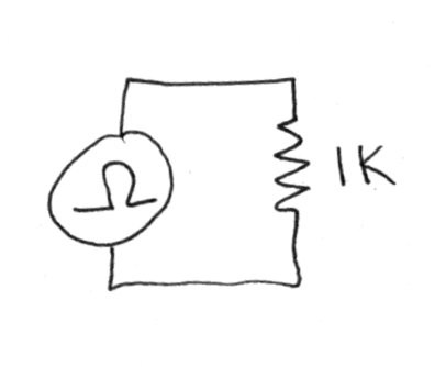
An ohmmeter applied across two terminals of an isolated resistor.
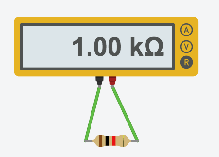
In Tinkercad the implementation should look something like this.
Start the simulation, then try the following:
changing the resistor value while simulating
observing the color code change
reversing the order of connections
finding the limits of the ohmmeter
Construct a circuit with a battery connected across a potentiometer, with a voltmeter (e.g. multimeter in voltage mode) measuring the potential between the wiper and negative.
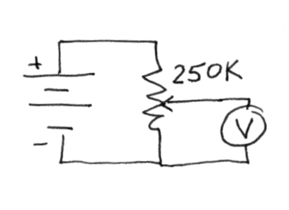
Measuring the wiper voltage of a potentiometer.
Start the simulation, then try the following:
adjusting the potentiometer dial position and observing the voltage reading change
changing the potentiometer resistance value
disconnecting the negative lead of the voltmeter
reversing the order of battery connections
Construct the following circuit with a battery, “pull-up” resistor, and pushbutton. Add a voltmeter across the switch. Please note that the Tinkercad pushbutton has redundant terminals: 1a and 1b are the same, 2a and 2b are the same.
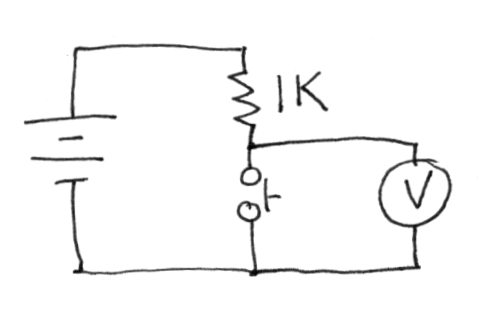
Observing the voltage drop across an open or closed switch.
The circuit is drawn with the resistor ‘pulling up’ the voltage to the supply voltage, but the switch and resistor topology can be reversed. How does this change the semantics of the measured voltage?
Construct the following circuit with a 9 volt battery connected directly across an LED. Please note that the positive terminal of the LED is named the ‘anode’ and the negative terminal the ‘cathode.’
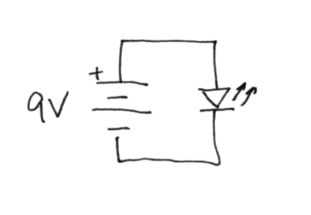
Burning out an LED.
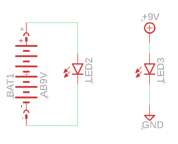
Burning out an LED, this time drawn in Eagle/Fusion 360. There are two versions for comparison: the left version uses a battery symbol, the right version uses an abstract supply notation.
The simulator should show a warning symbol over the LED, with a rollover message explaining the condition. What happens using the 3V battery instead?
Construct the following circuit with a 9 volt battery connected through a resistor to an LED. Please add an ammeter (multimeter in current mode, marked ‘A’) in series, and a voltmeter across the LED.
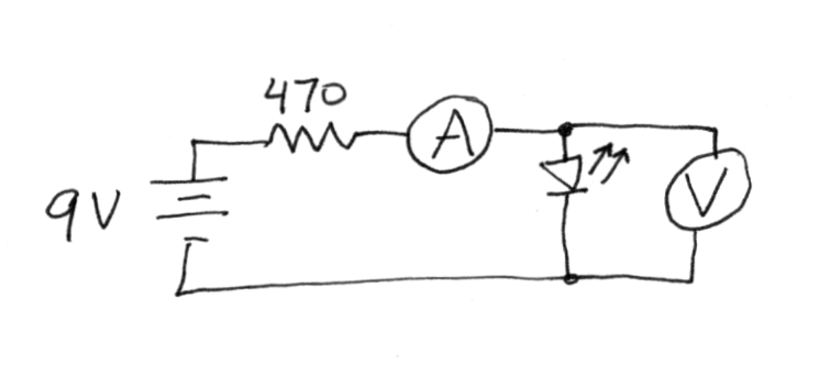
Measured the voltage of a ballasted LED.
The circuit is drawn using a 9V battery and 470 ohm resistor. What range of resistance values will still light the LED?
What is the calculated voltage across the resistor? Can you independently calculate the current through the resistor to verify the measurement?
Construct the following circuit with a 9 volt battery, switch, resistor, and LED. Please note that you could either a pushbutton (SPST) or slide switch (SPDT).
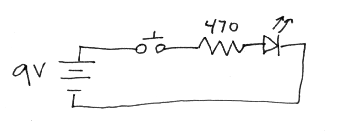
Simulated flashlight.
Construct the following circuit with a 3 volt battery, photocell, resistor, and voltmeter across the resistor.
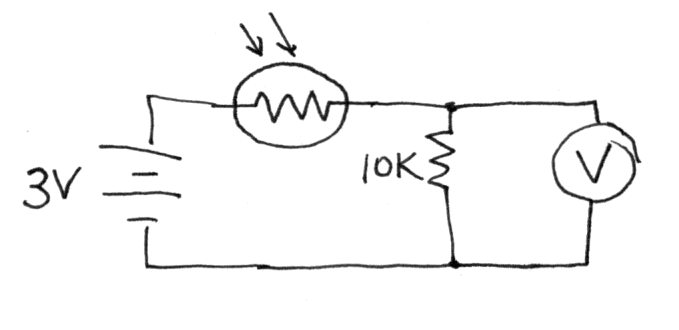
Illumination sensor circuit.
Click on the photocell and vary the simulated illumination. How does the voltage vary?
What range of resistance produce a reasonable variation in measured voltage?
Try using the ohmmeter to measure the range of a second (disconnected) photocell.
Deliverables
The result of your explorations should be a single circuit sketch containing the following circuits:
Resistor, ohmmeter (multimeter set to resistance mode).
Battery, potentiometer, voltmeter.
Battery, switch, resistor, voltmeter.
Battery, LED.
Battery, LED, resistor, voltmeter, current meter (‘ammeter’).
Battery, switch, LED, resistor.
Battery, photocell, resistor, voltmeter.
When it is time to submit your circuit for the assignment, you’ll need to click Share, then Invite people. You may then copy the generated sharing URL and submit it to Canvas.
N.B. As of Fall 2020, Tinkercad has a sharing bug, please note the following. Tinkercad Circuits sketch sharing links which include the term ‘tenant=circuits’ appear consistently to return a 404 error instead of accessing the sketch. The first workaround appears to be to exit and reload the sketch at least once before generating the share link. Alternatively, an existing link can be fixed by editing out the tenant=circuits clause, e.g. delete the text ‘?tenant=circuits’.
Challenges
If you would like to explore more, please consider the following optional challenge questions.
Try constructing a Wheatstone bridge. This is a classic four-resistor bridge circuit used for measuring tiny variations in resistance, e.g. from measuring forces with a strain gage.