Oscilloscope Guide
The IDeATe Physical Computing Lab equipment includes digital oscilloscopes for visualizing electrical signals as a function of time. The following notes may help you in basic use of our oscilloscopes. If any terms are unfamiliar, please consult the Glossary below.
Models and Datasheets
We have two models in stock. For most purposes these are interchangable, but one of them does have better high-frequency capabilities:
Model |
input channels |
bandwidth |
sampling rate |
|---|---|---|---|
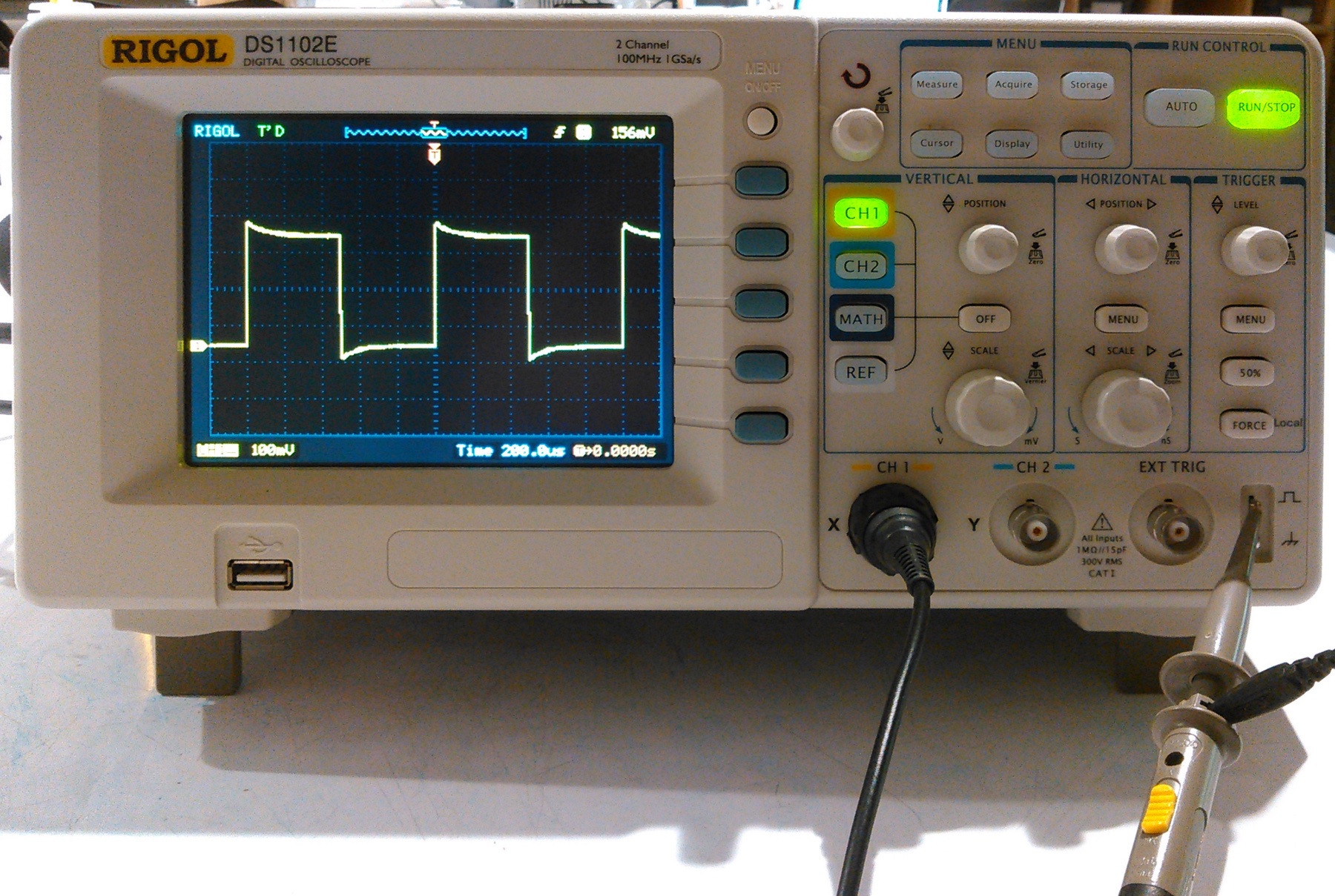
Rigol DS1102E |
2 |
100 MHZ |
1 GigaSample/sec |
Rigol DS1052E |
2 |
50 MHz |
1 GigaSample/sec |
Both of our models are described by the same Rigol User Manual. Other related documents can be found on the Rigol 1000 Series product page.
Common Controls
The various knobs related to the on-screen menus have multiple functions depending on mode and context. A general guide:
- Menu On/Off
A white button near the upper right corner of the screen, the usual way to summon or hide the on-screen menus. (Note that the menu also appears after activating a channel or pressing a gray button.)
- gray buttons
The five gray buttons to the right of the screen usually correspond to adjacent menu options.
- input knob
The white knob to the right of Menu On/OFF is both a rotary selector and a momentary switch for indicating a choice.
- AUTO
In the upper right corner under ‘Run Control’ is an AUTO button which initiates an auto-setup which attempts to set the display parameters properly for a given signal. When it works, it eliminates a number of the setup steps listed on the checklist, but it can also fail to capture the signal of interest and leave the horizontal and vertical controls set to extremes.
- probe compensator
At the lower right corner of the face are two output lugs which produce a reference signal. These can be used to adjust the probes but also provide a convenient practice signal. E.g., try clipping a probe to the upper lug and pressing AUTO; the scope should resolve to showing a square wave.
Operational Checklist
Place the scope in a convenient location and turn it on. It takes a few seconds to boot up.
Make sure you have one or two probes as needed. Make sure each probe is set to 1X (unless you need a high voltage range). Attach the probes to the X and Y inputs. If using only one probe, use X.
Activate one or two channels as needed using the CH1 and CH2 buttons. E.g. for measuring a single signal on CH1, make sure only the CH1 button is lit. Pressing a channel button can cycle between activating the channel on-screen menu or turning off the input.
When starting for the very first time, you may wish to reset all modes to the original factory setup. This is also useful if you find a scope in a deeply unfamiliar state. The original configuration can be reloaded from the Storage menu:
Press Storage to activate the menu,
press the top gray switch to activate the Storage submenu,
purn the white knob to scroll down to Factory,
press the white knob to select,
then press the center gray button to confirm with Load.
Reset the vertical channel controls. When in doubt, the following settings are a good starting point:
Coupling
DC
BW Limit
OFF
Probe
1X
Digital Filter
OFF
Volts/Div
Coarse
Invert
OFF
Reset the horizontal controls. When in doubt, the following settings are a good starting point:
Delayed
Off
Time Base
Y-T
Trig-Offset
(select to reset)
Reset the trigger controls. When in doubt, the following settings are a good starting point:
Mode
Edge
Source
CH1
Slope
Rising ege
Sweep
Auto
Coupling
DC
Sensitivity
0.38div
Holdoff
500 ns
Set the vertical gain using the Vertical SCALE knob to match the expected signal. E.g., for typical digital logic, either 1.0 or 2.0 Volts/Div will plot legibly. This knob is shared between both channels, so you may need to use CH1/CH2 to select. The vertical scale value is shown onscreen in either yellow or blue.
Set the vertical offset using the Vertical POSITION knob to place the zero voltage point at a convenient height. For our typical positive signals, it is often convenient to set the zero near the bottom. This knob is also shared between channels.
Set the time axis to a reasonable value using the Horizontal SCALE control. This is shown on screen as the white Time value and represents the horizontal time per division.
The correct value depends entirely on the circuit under test. E.g. for audio signals in the 1KHz range, a good value would be 1 ms/div to capture one oscillation cycle per division. Or for an SPI bus at 1MHz, that same scale might show entire data packets, but 1 usec/div would show individual clock cycles.
Zero the horizontal position using the Horizontal POSITION knob. This will leave the trigger point, marked with an orange T, in the middle of the screen, showing a little of the signal before and after the trigger event.
Identify the physical locations of the signals of interest in your circuit.
Identify locations in the circuit you can ground the scope using one or both probe alligator ground clips. You may need to use an extension wire if it is not conveniently close to the points of measurement. Attach the ground clips.
Make sure the Run Control RUN/STOP button is glowing green. If it is red, press it once to toggle. (If it stays red, the scope trigger settings may be in single-sweep mode instead of auto or normal.)
Touch the CH1 probe to the signal point. For wires, components, and DIP leads it is usually possible to clip the probe tip in place. For circuit traces and surface-mount devices it is necessary to hand-hold it. Please take care not to short out any adjacent signals in the process.
If no trace at all is shown, you may need to adjust the trigger. Pressing Trigger 50% may set a workable mid-range value. Otherwise turning the Trigger LEVEL knob may allow you to find a voltage point within your signal which produces a reasonable trace.
If that fails, you might check that your vertical settings are correct for your actual signal. The scope can plot the trace off-screen if the gain or offset place it out of range.
If that fails, you may need to review all other settings. Keep experimenting until you see something.
Next Steps
These scopes offer a wealth of other features. Once you master the basics of showing a signal, you might consult the manual to attempt the following:
Making an onscreen numerical voltage measurement.
Measuring frequency of a periodic signal.
Observing two signals at once.
Usin one signal to trigger measurement of another.
Using a variable holdoff to show sparser cycles of a highly variable periodic signal.
Using a delayed sweep to show one signal at two different time scales.
Saving a trace to a file on a USB stick.
Glossary
- oscilloscope
A electronic test instrument which plots voltage as a function of time. Frequently shortened to ‘scope’.
- digital scope
A digital scope is essentially a computer which uses a digital-to-analog converter to measure a voltage by sampling it over time, then plots the result on a display. These can also perform a number of measurements on the data, including frequency, period, limits, and averages.
- probe
A hand-held instrument for connecting an electrical signal to the scope. Our probes have a yellow 1X/10X attenuation switch and terminate in a female BNC connector which mates with the CH1 or CH2 connectors on the oscilloscope.
In general, we recommend using the 1X setting to minimize confusion, unless signals greater than 100V need to be measured. The 10X attentuation will switch in a voltage divider to reduce the signal actually reaching the oscilloscope input.
- trace
The line plotted for each signal. On the Rigol, this is by default drawn in yellow.
The name stems from analog oscilloscopes which use a cathode-ray vacuum tube as the display; the trace is literally the visible path of a beam of electrons sweeping across the display. A digital scope retains the term although the mechanism is entirely different.
- channel
An independent analog input amplifier. Our oscilloscopes are two-channel, so two signals may be simultaneously connected and plotted.
- bandwidth
An analog measure of the frequency range for each channel amplifier. Bandwidth is conventionally specified as the -3dB (half-power) attenuation point, so signals at this frequency will be somewhat reduced, and the response will roll off rapidly at higher frequencies.
- sampling
The voltage measurement process which produces a digital (numeric) estimate of voltage at discrete points in time. The oscilloscope shares the sampler between the channels, so the reconstruction of the waveform depends upon a number of modes. E.g., the scope may alternate measurements between channels for nearly simultaneous measurement of two inputs. Or for periodic signals, it may scatter measurements over multiple signal cycles so the final displayed trace is a composite over multiple periods.
- sweep
One cycle of plotting trace(s) from left to right.
- vertical
The controls related to the vertical voltage dimension, primarily gain and offset.
- horizontal
The controls related to the horizontal time dimension, primarily the time scale. Note that our scope displays can range from as slow as 50 seconds/division (for long-term processes) to as fast as 2 nanoseconds/division.
- trigger
The controls related to positioning a trace horizontally, primarily trigger level. In many cases an oscilloscope is used to show a repetitive signal which is most easily viewed when successive plots show a similar phase of the signal. The basic edge trigger mechanism delays the start of a sweep until the input reaches a particular trigger level and direction (either rising or falling). This heuristic often allows beginning each sweep at the same signal phase, but can setting correctly can require user intervention. There are additional trigger methods for other kinds of signals.
- graticule
The grid of dotted lines shown in the display for estimating measurements.
- division
One grid unit, either vertical or horizontal. The Rigol scopes show eight divisions vertically and twelve divisions horizontally.