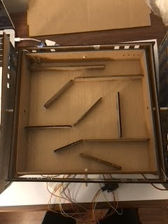
For this round of development, we added the floor of the maze and the joystick module to our 2 axis gimbal system.
#include
const int outerServoPin = 5;
const int innerServoPin = 4;
const int jsXPin = A0;
const int jsYPin = A2;
Servo outerServo;
Servo innerServo;
int outerRotStart = 90;
int innerRotStart = 90;
int outerRotMin = outerRotStart – 60;
int outerRotMax = outerRotStart + 60;
int innerRotMin = innerRotStart – 60;
int innerRotMax = innerRotStart + 60;
int xPos;
int yPos;
int outerPos;
int innerPos;
void setup() {
// put your setup code here, to run once:
pinMode(jsXPin, INPUT);
pinMode(jsYPin, INPUT);
Serial.begin(115200);
outerServo.attach(outerServoPin);
innerServo.attach(innerServoPin);
outerServo.write(outerRotStart);
innerServo.write(innerRotStart);
delay(1000);
}
void loop() {
// put your main code here, to run repeatedly:
xPos = analogRead(jsXPin);
yPos = analogRead(jsYPin);
outerPos = map(xPos, 0, 1023, outerRotMax, outerRotMin);
innerPos = map(yPos, 0, 1023, innerRotMax, innerRotMin);
outerServo.write(outerPos);
innerServo.write(innerPos);
delay(250);
}
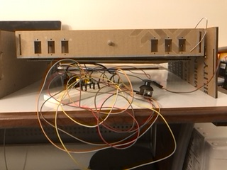
Adding the joystick allowed us to test out a basic playfield. We added horizontal supports to better balance the system, however they are not shown in the video in order to better see the circuit and handle the motors during testing. We re-laser cut the frames out of cardboard because we are still trying to optimize our dimensions and we knew we would go through several iterations with minor adjustments when we were assembling. We did use bearings this time, however we are still working on making the tilt smooth. We also realized that our previous design with the paper clip linkage going through the hole would work better with a slot in order to add a degree of freedom and not strain the frame.
Leave a Reply
You must be logged in to post a comment.