During these pandemic times, it becomes increasingly difficult to stay connected with peers. This raises concern involving communication among people but also brings forth the need for telepresence. For our project, we used computer vision and facial recognition components to detect human eyes and send that information to an arduino that controls the movement of a device which will reproduce the idea of Mona Lisa’s eyes. Instead of having the Monas Lisa follow the person looking at it, since we were trying to establish a connection among a diverse set of people, our device replicates the partners eye movements. The goal of this project is to enhance connection among people. We were able to utilize and create a fully functional computer vision software that detected eye movements, a communication channel that sent information from the eye detection software to the arduino of the other person, and a working device which responded to the data received and produced a physical motion that corresponded to the eye movements.
Project Goals
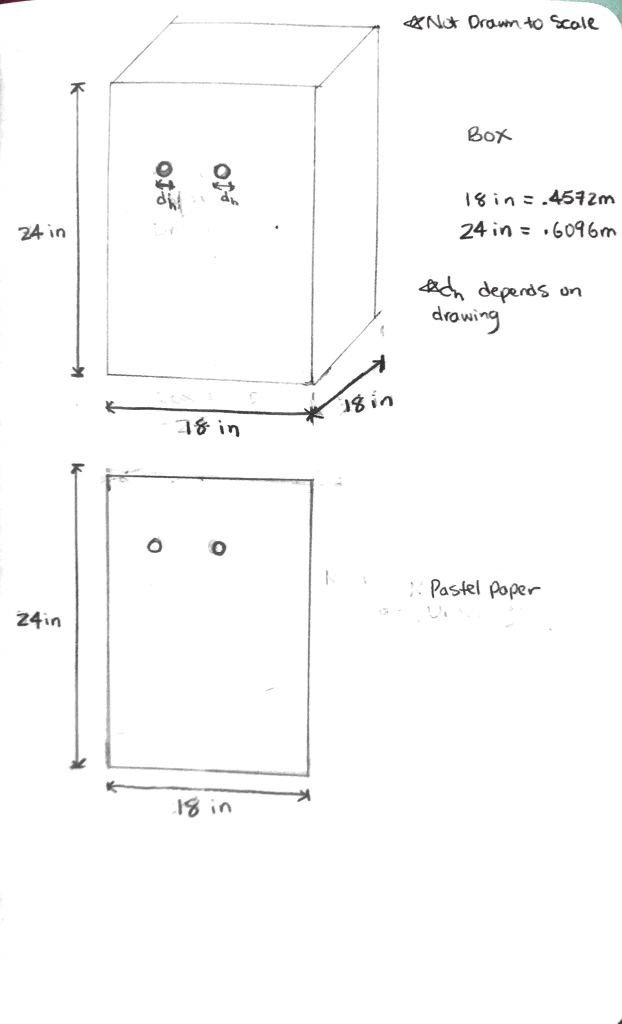
Our goals throughout the project were to convey personality through eye movement which enhances the telepresence interaction, as well as elicit an amused yet shocked reaction. The MVP of our project was to create a working prototype that would move Mona Lisa’s eyes. This meant having facial, eye, and pupil recognition using opencv, an arduino that would receive messages over an mqtt server, an animatronic eye on a 2 axis gimbal to replicate eye movements, all placed into a box with a Mona Lisa drawing in the front. This is how the eye was set up:
Initial Design
When I began writing the code for the pupil detection there were a few choices to make in terms of the implementation. Since there does not exist a ML model that detects pupils like there are for faces and eyes, I had to be a little more creative in order to detect the pupil. I decided to use blob detection to locate the pupil. The idea was that the largest blob within the eye frame would be the pupil. In opencv, in order to do blob detection you first need to make the image grayscale. At first, to determine where the blob was, I applied a threshold on the grayscale image in order to limit certain pixels from showing up. Ideally, this would cause the pupil to stay, while removing unwanted pixels. However, this had several issues, because this logic heavily relied on finding the perfect threshold value. This wasn’t good, especially because lighting played a huge role in determining that value. Thus, I decided to go with a different design that would find the contours of the eye frame and then pick the pupil based on blob sizes that appeared. This resulted in a more well-defined solution that limited external factors. Another important decision was where in the code the transformation of data would occur. There were two possible places that this could happen in. The first option was on the python end, meaning that before sending the message to the arduino, the python code would convert the data into its appropriate angles. The second option was to convert the data into angles on the arduino end. Upon receiving the data, the arduino would convert the relative pupil distances into angles. I chose to convert the angles on the python end, because it made more sense to do the heavy lifting all on the python, and simply have the arduino read the data and execute the servo motion. Another important design decision was the use of the mqtt code provided through the class resources. When I first began implementing the mqtt server connectivity I was planning on making my own program to send messages. However, reusing the existing bridge program code saved me many hours that I would have spent trying to figure out how to use that.
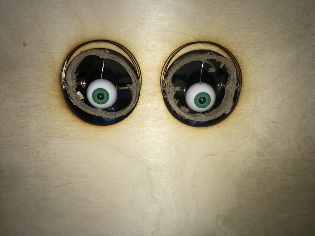
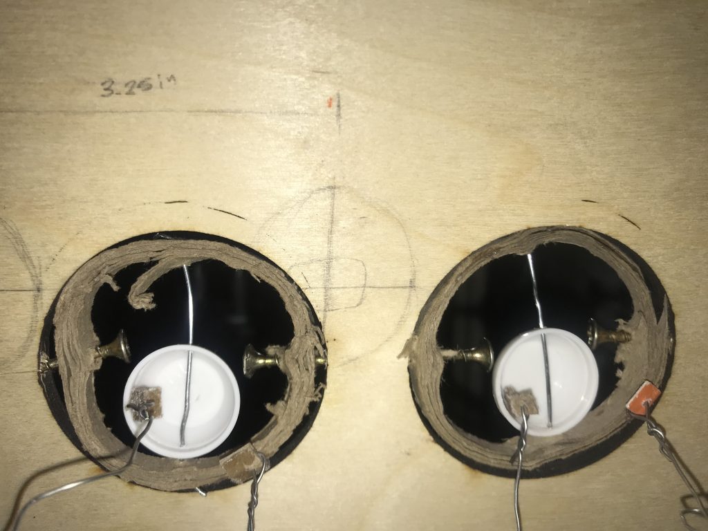
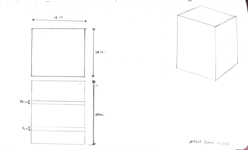
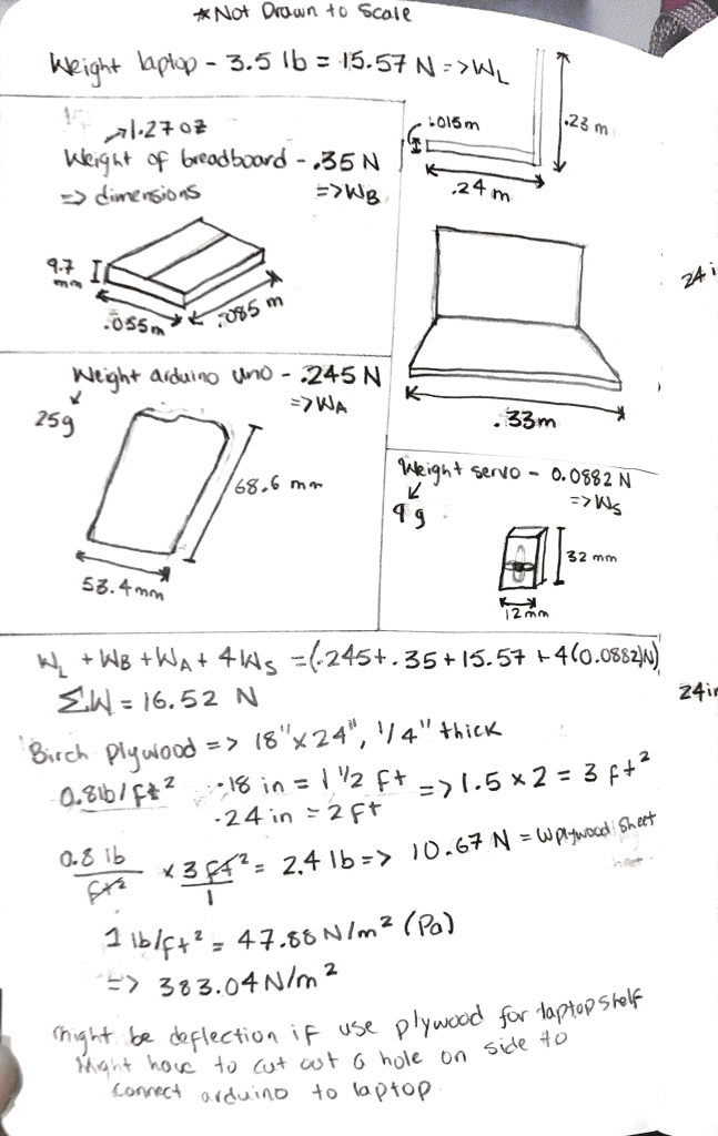
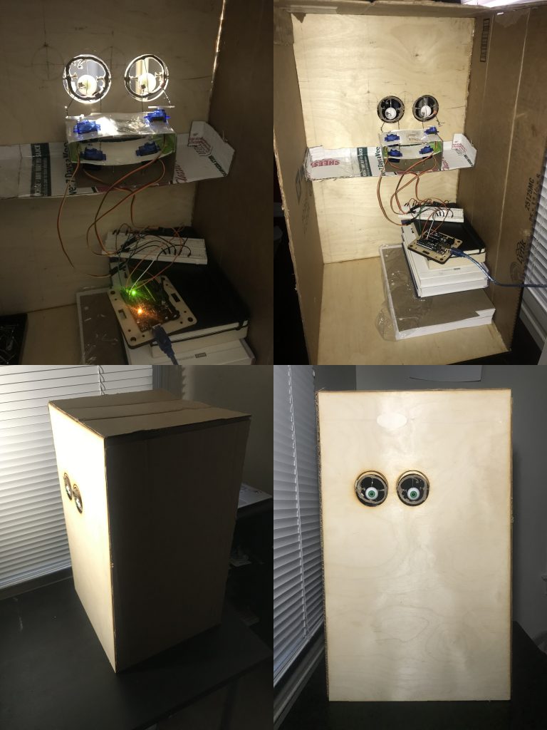
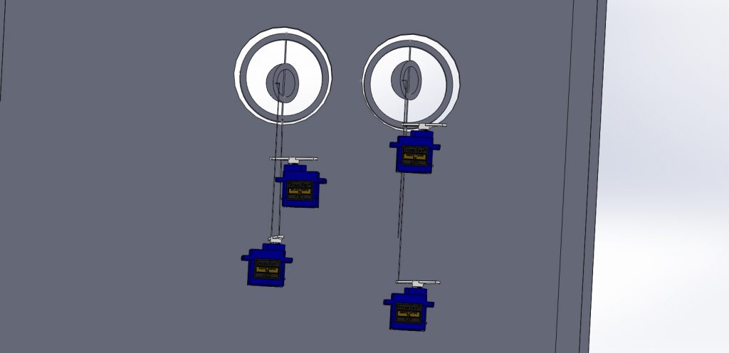
When we thought about creating the eye structure, there were several ways online to go about it. We decided to use the method where we used a 2 axis gimbal to portray eye movement. We didn’t want it to be so complex that we couldn’t achieve it, but we also wanted to create a somewhat realistic eye movement experience. Initially, we decided to use clay to model the eyeball.The clay ended up being too weak to support the wire movement, and it also absorbed the glue that was used on it to attach the l-brackets. Therefore, we switched to plastic eyeballs, as they provided us with a more realistic eye feature for the artwork and didn’t cause any of the problems that the clay eyeballs did. Due to uncertainty regarding using TechSpark, we were unable to change some of the cardboard features for the box to plywood. We also couldn’t add an extra shelf, like we intended, so we decided to use books to place the arduino and breadboard on. The intended structure can be seen in the following images:
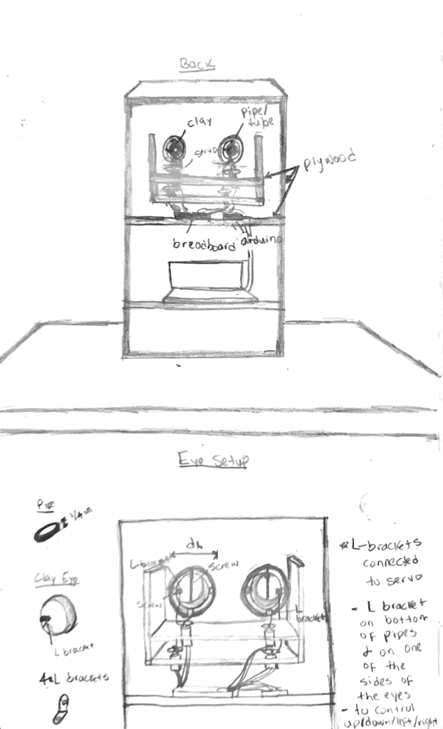
Another feature we had issues with was the paperclip linkages that connected the servo horn to the animatronic eyes. They were not flexible enough, so we decided to use some soldering wire. The CAD model that we created, was also unable to move, due to the rigidity of the linkage connecting the servo to the eye and the fixed position of the servos. Unlike We couldn’t represent the soldering wire in the CAD model, but the physical changes we made were successful. The eye structure was able to move according to the messages it received over the mqtt bridge.
This can be seen in the video below:
Future Plans
The next iteration of this project would be to create a replica of the device. The initial design included a pair of systems intended to be controlled by each person. Having two devices would allow for a richer connection between the users, as they can both act as the controller (person who controls device) and receiver (person who sees output of eye movements) simultaneously. Another idea we had to convey personality was by adding a blinking feature. This would provide the device with a more human-like action.
Task Breakdown
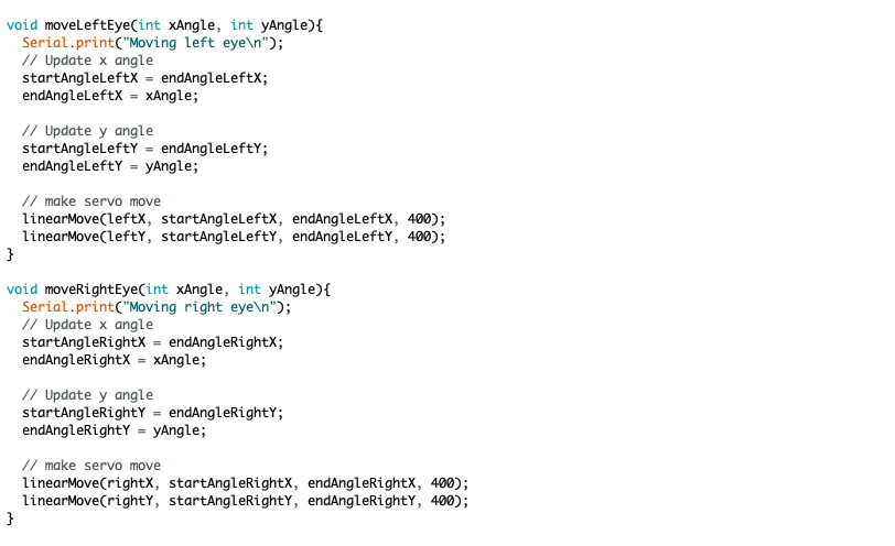
Max wrote the code for the pupil detection, integrated the mqtt server to send messages to arduino, and wrote arduino code to move servos. Marione created the CAD designs, animatronic eye, and the mona lisa box. These can be seen below:
Code Implementation Details
If you want to look more in detail into the code it can be found here: https://github.com/mdunaevs/Eye_Tracking
Or downloaded as a zip:
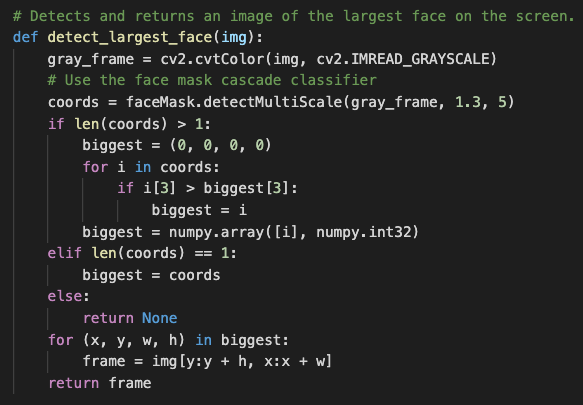
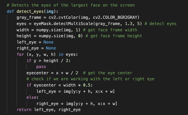
In order to recognize a pupil, first we need to detect a face, and from that face we need to identify the persons eyes. The same principle can be applied in programming. Opencv allows for easy extraction of a person’s face and eyes using cascade classifiers (machine learning approach to detect objects within an image. In my code, I made use of these classifiers so that I could detect a persons’s face and eyes. In the functions shown below, I am converting the image into a grayscale and then feeding it to the classifiers. The classifiers then come back with a set of coordinates representing the detected objects, which contain information about the position, minSize, and maxSize of the object. The third index of the tuple represents the maxSize. Using the information about the maximum size, I can determine which object is the largest, which represents the object I am looking for.
Now that we had the eyes isolated, we needed to get the pupils. However, the issue was that unlike that face and eyes there currently does not exist a cascade classifier for a pupil. This meant I had to get a little more creative with how to extract the pupil. As mentioned before, the concept behind the classifiers were to detect regions / objects within the image. Following a similar approach I decided to attempt to detect large objects within the eye frame.
My solution to this was to use blobs. A blob is a group of connected pixels in an image that share some common grayscale value. By finding all the blobs within the eye frame, I can use this information to find the appropriate blob corresponding to the pupil.

Now that the we were able to locate the pupil of the eye, we needed to figure out how to send some sort of data relating to the pupil to the arduino. To begin with, we defined what our data would represent. Our data represents the angle to move the arduino. The way we calculated the angle was by first computing the distance between the expected location of the pupil (based on center position of eye frame) and the actual location of the pupil (based on position within the frame).
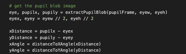
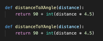
Once we had the distance we applied a conversion to change the distance into an angle. Note that the constants were found by experimenting with the data and trying to get a reasonable angle change.
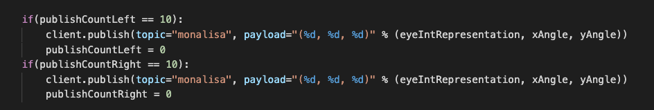
Now that we had data, this needed to be sent to the arduino. The data was sent over an mqtt server. Using the same bridge program we had in class, we were able to send data to the arduino.
Then when the data was received on the arduino end, we were able to move the servos.
At this point the code was working properly, however in order to get a ricer eye movement experience, we decide to incorporate saccade movements. A saccade refers to the sudden, quick, simultaneous movement of both eyes in the same direction.
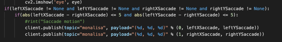
The trick to this was determining what was considered a saccade motion. Since saccade motions are typically quick and sudden jolts of both eyes, if we had to map every saccade motion to an arduino movement, it would result in the same issue as before, where too much data is being sent to the arduino in too little time. Thus, I created a filtering system to only acquire the saccades in which the ending position of the pupils relative to their eye were roughly in the same position. Based on the data and tweaking the value around 5 was a reasonable number used to determine whether the distances of the pupils were relatively close to one another.
CITATIONS
http://www.pyroelectro.com/tutorials/animatronic_eyes/hardware_servos.html
https://medium.com/@stepanfilonov/tracking-your-eyes-with-python-3952e66194a6
https://gist.github.com/edfungus/67c14af0d5afaae5b18c
Supporting Material
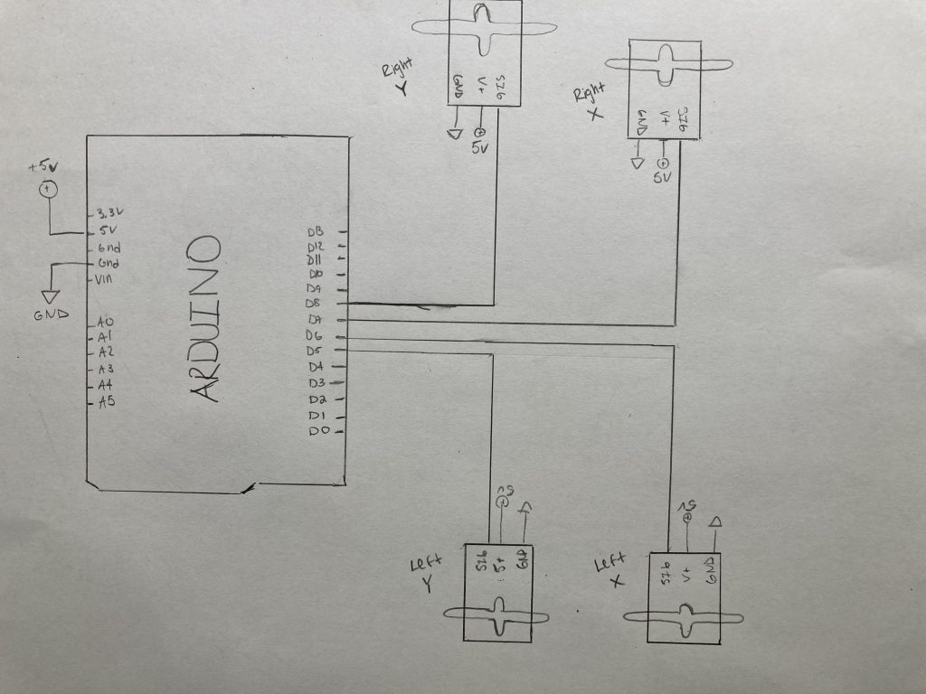
Electronic Schematics:
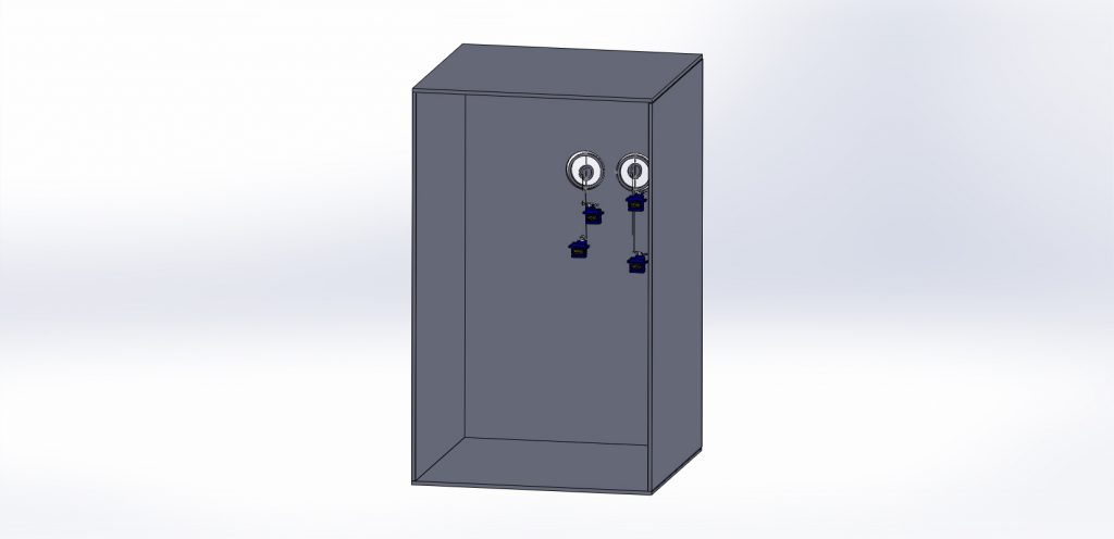
CAD Files:


Leave a Reply
You must be logged in to post a comment.