Day 9: (Wed Sep 29, Week 5) Photointerrupter in Action
Notes for 2021-09-29.
New Assignments
New assignment, due next class: Exercise: Reactive Marble Run Tile.
Agenda
Summary electrical theory review.
Introduce new assignment.
Demo of reading a switch with a Pico.
3.3V vs 5V circuits
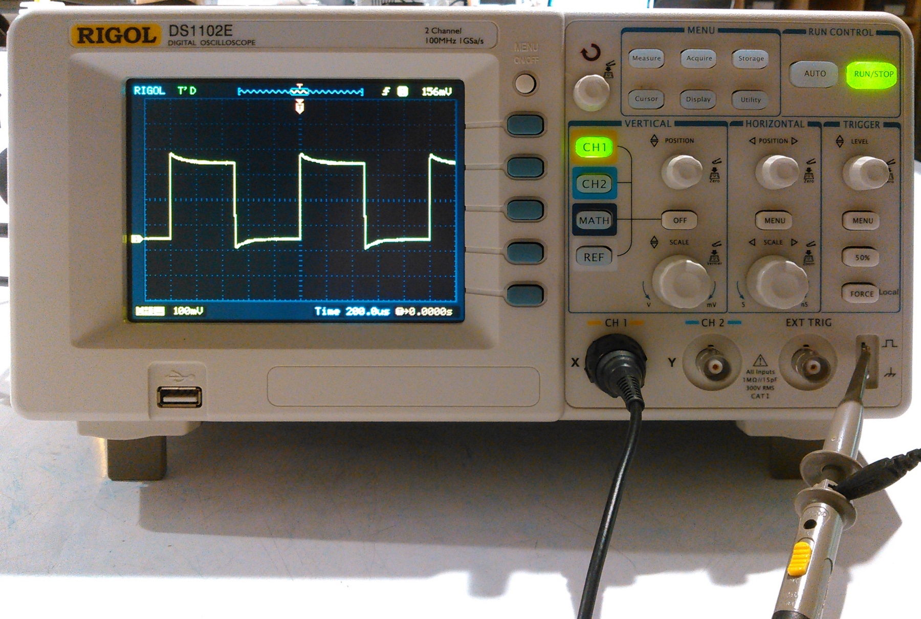
Oscilloscope demo.
Sample code walkthrough: digitalio, logic levels, state machines, hysteresis.
Sample CAD walkthrough.
Sensor lead extension and heatshrink demo.
Hand out a few more parts from the F21 Course Kit (1931, 6049, 482).
In-class sketching, prototyping, and individual design review.
Supplementary Video
Electrical Theory Introduction: https://youtu.be/d5HxmQHCO48
Kirchhoff’s Laws, Ohm’s Law: https://youtu.be/hnbD_D4ljOE
Resistors and Voltage Dividers: https://youtu.be/j8rvBSPiiUI
Switch and LED Circuits: https://youtu.be/lY3ckgUBEbg
Reflective Photointerruptor: https://youtu.be/atuFgbVYVsA
Resistive Circuits in Tinkercad: https://www.youtube.com/watch?v=mX5L67WcWec
Photointerrupter Circuit
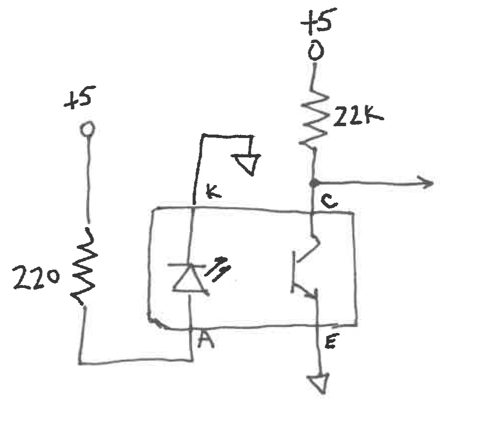
A photointerrupter circuit includes a current-limiting resistor for the LED and a bias resistor for the phototransistor.
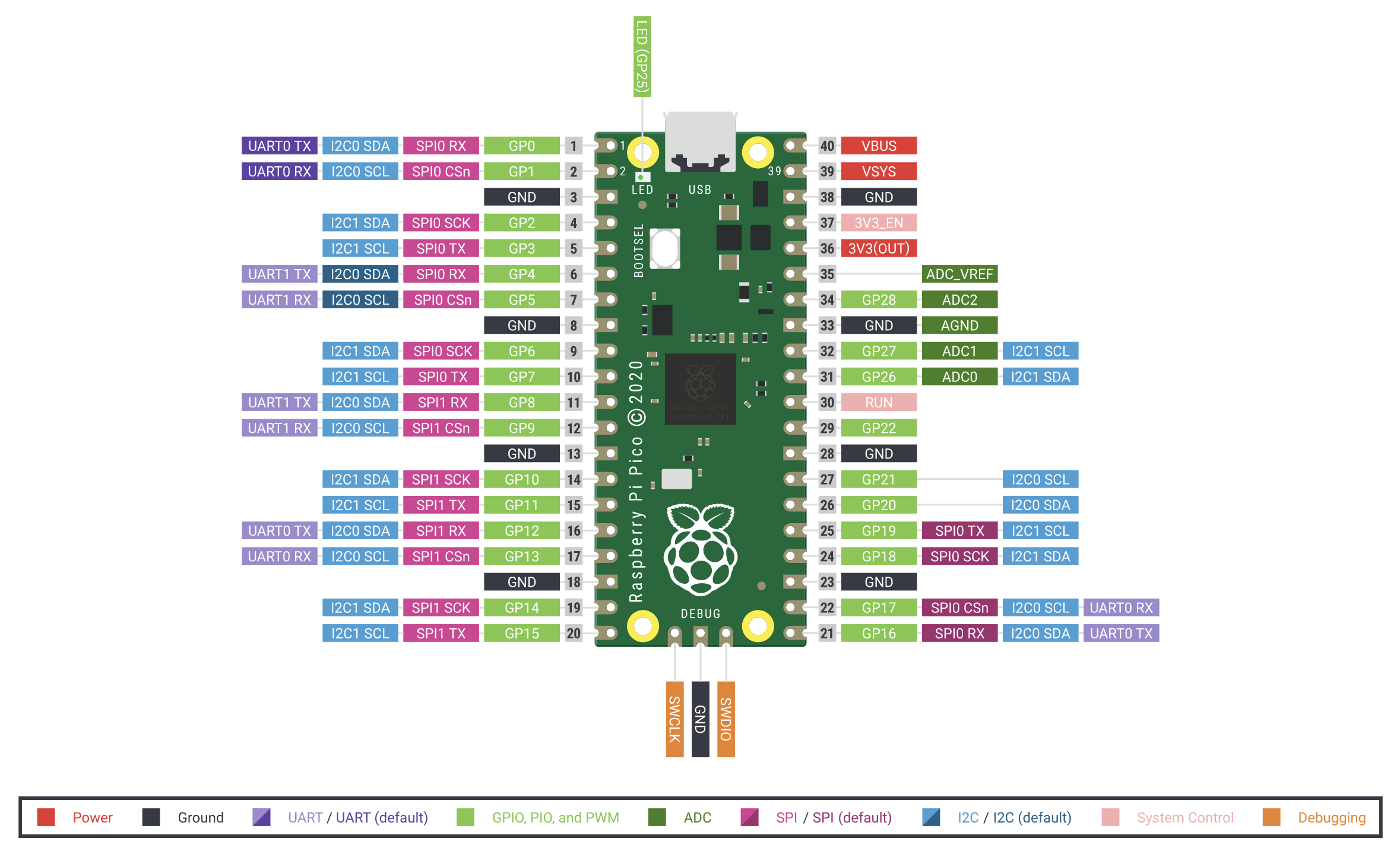
Raspberry Pi Pico diagram of pin functions.
Essential Lab Equipment
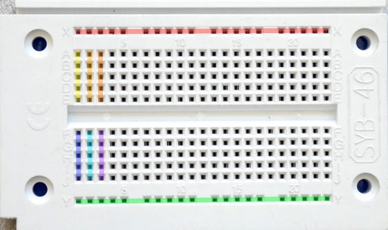
Solderless breadboards are our workhorse for electronics prototyping. Each short row of five holes connects together by an internal metal clip and forms a single circuit node. Each long bus row is a node. Please disregard the +/- bus labels on your breadboards.
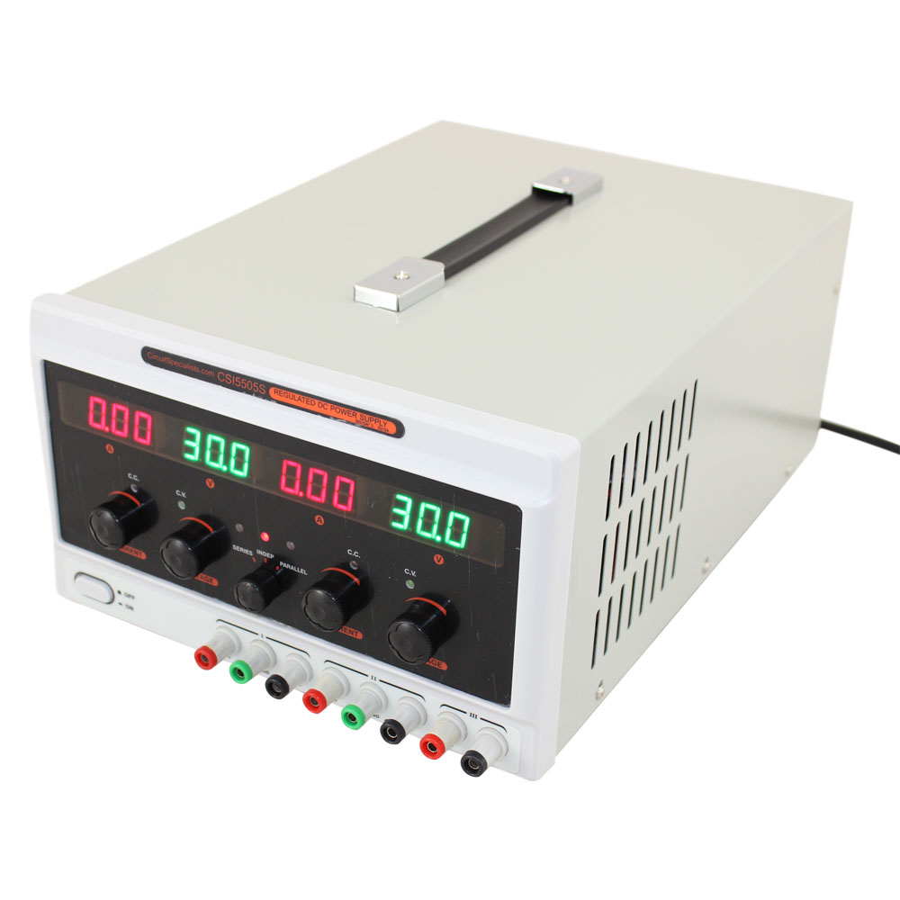
Three-channel lab power supplies.

Digital multi-meter (DMM).
Digital oscilloscope. For more details, please see Oscilloscope Guide.