Exercise: Servo Motion with the Pico
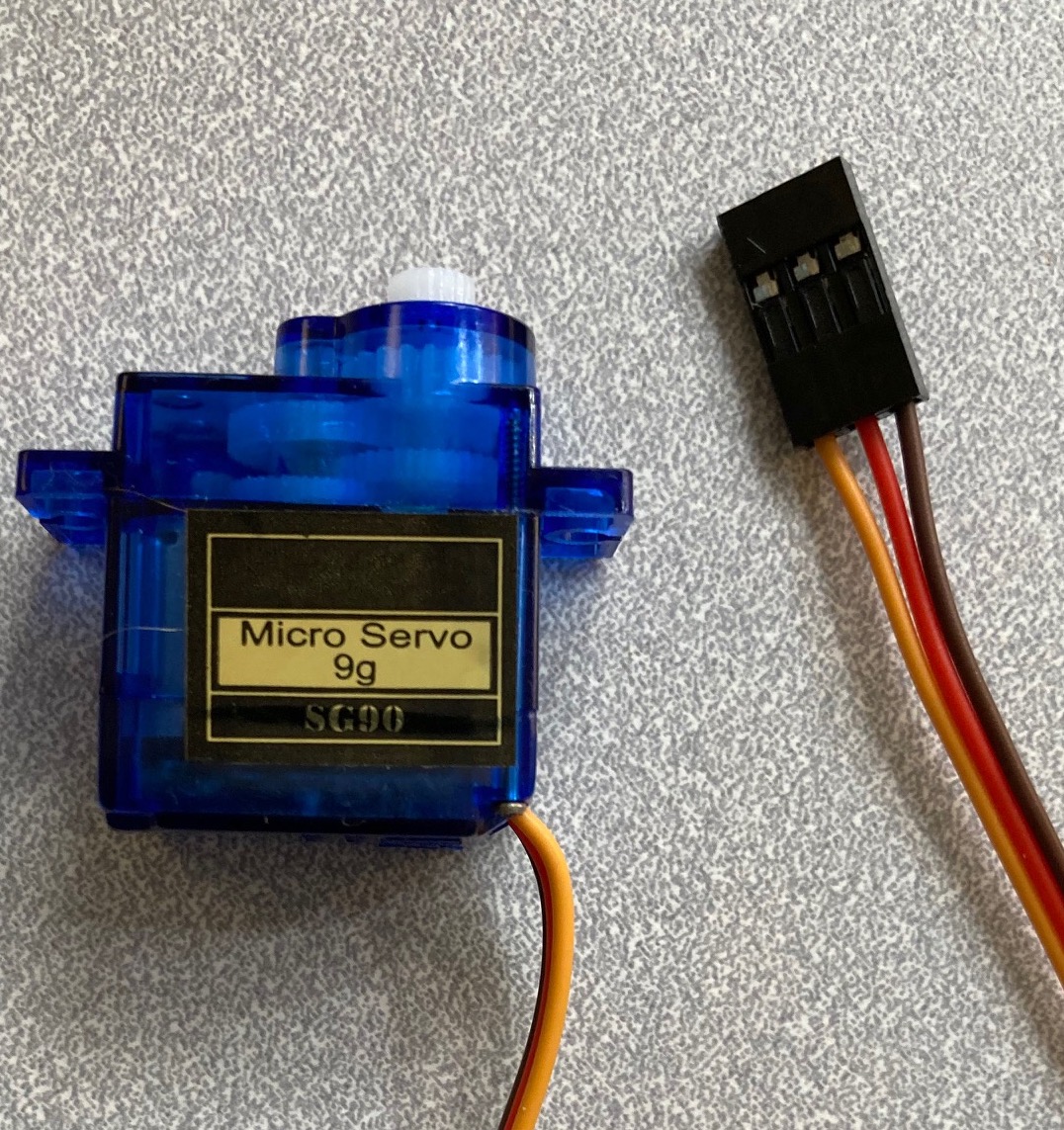
The most convenient device for creating movement in the course kit is the hobby servo. These are feedback-controlled motors which move an output shaft to a specified angular position. The chief limitation is a limited range of travel, typically 180 degrees of rotation.
This exercise is primarily about programming style, the main objective to practice structuring a program as parameterized functions. But even though the focus is not on mechanical design, you are encouraged to rig up a simple moving apparatus using the servo, even with basic materials such as paper, tape, cardboard, or paper clips.
Objectives
After this exercise, you should be able to:
Control a hobby servomotor module.
Structure a scripted action sequence as parameterized functions.
Write code with integrated debugging using the serial port for user console communication.
Reference Guides
Please review the following reference guides as needed:
Programming section of the course Reference Guide
Steps and observations
The overall objective is to create a choreographed servo movement using a program structured around parameterized functions.
Please attach a single hobby servo to your Pico as described in the figures. Please wire carefully and pay attention to exact placement; the circuit is powered from your USB port, it would be best not to create any short circuits.
Please write a CircuitPython program to generate patterned movements with the servo. You may wish to start with one of the sample programs. For this exercise, there is no prescribed user input, the movements will be performed autonomously over time.
For this exercise, I require that your structure your program around parameterized functions. The best choices of structure depend upon your objectives, but here are some suggestions:
Functions that produce a short motion sequence to use as a compositional phrase or primitive. The parameters might relate to position, rate, or repeat count.
Functions that produce an algorithmically generated movement, i.e. one based on iterated calculations without scripting data.
Functions that produce a pseudo-random motion (see CircuitPython random number module). The parameters might relate to the position, scale, tempo, or duration.
Functions that produce stillness. It’s an artistic question whether that is pure motionlessness or an active quiet.
Functions that represent larger units of choreography and only call motion primitive functions instead of directly issuing servo commands.
Please implement your ideas in code, then test and iterate. Please add debugging output to the serial monitor as needed.
Deliverables
The result of your explorations should include:
A brief paragraph describing your choreographic intent and outcome, submitted as a blog post to the course site. This may be private if you prefer.
A CircuitPython program, submitted as a properly-formatted block within the post. The program should implement a hobby-servo choreography controller, and be structured as multiple parameterized functions.
A live in-class demo at the start of class on the due date.
Challenges
If you would like to explore more, please consider the following optional challenge questions.
Can you construct a simple apparatus moved by the servo?
Try adding additional servos with coordinated movements.
Can you structure your program to issue commands to multiple servos asynchronously?
Can you use a Python generator function to produce a sequence of servo angles?
Figures
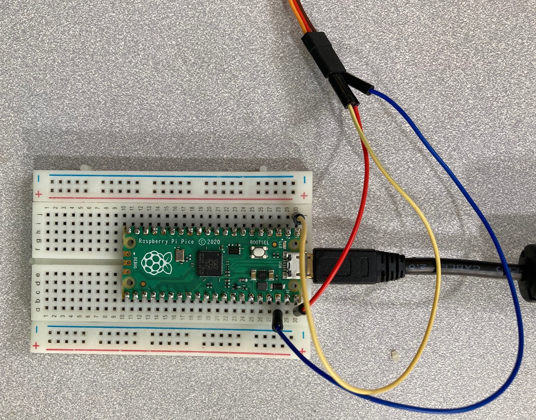
A basic wiring setup for the exercise. The Pico has header pin row soldered on both sides. The red jumper wire in pin 40 (VBUS) connects the USB +5V to the servo red power input. The blue wire on pin 38 (GND) connects ground to the servo brown ground input. The yellow wire on pin 1 (GP0) connects the control signal to the servo orange signal input. Note that the jumper wire colors themselves are not critical, but consistency helps with recognizing mistakes.
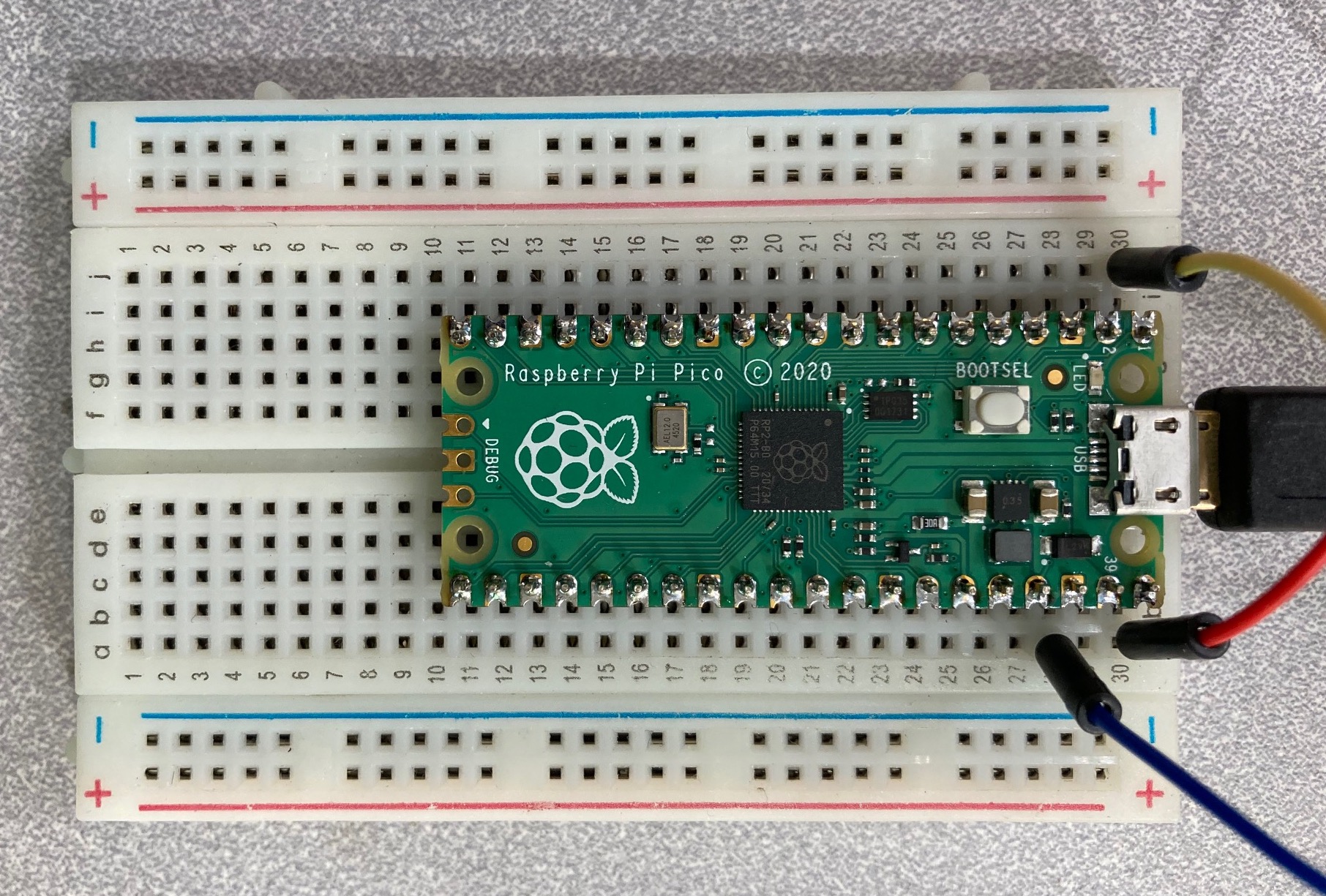
Detail of the jumper wires connecting to the Pico. Each short row of five sockets on the breadboard connect together, so the jumpers wires connect to the adjacent Pico pin.
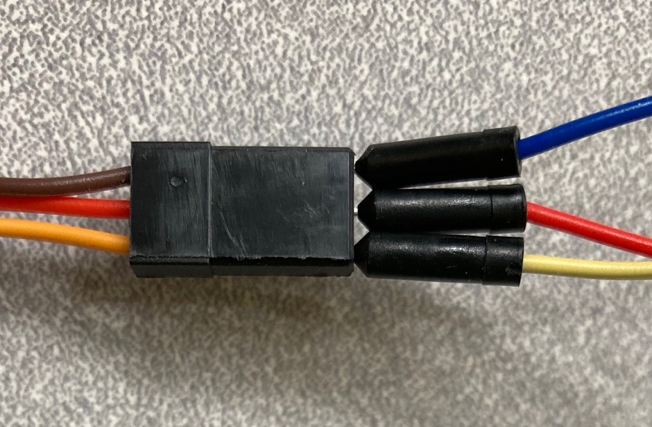
Detail of the jumper wires connecting to the hobby servo. The servo has a female socket header, so the jumpers wires can directly connect, albeit the retention is weak.
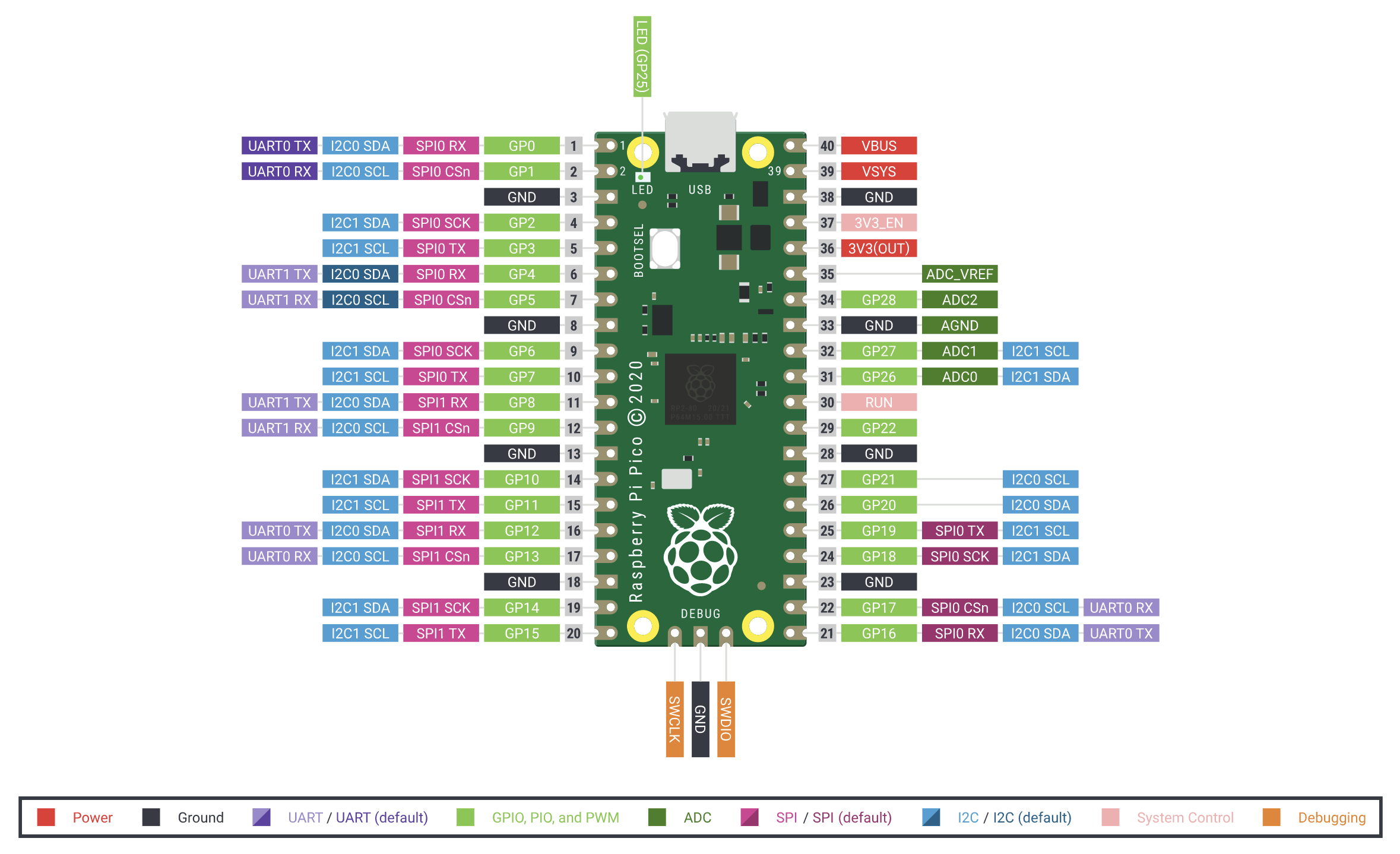
Pin diagram of the Raspberry Pi Pico.