Design Example: GT2 Timing Belt Drives (3D Printed)
Timing belts are an efficient way to transmit motion and energy. A more general discussion of designing with timing belts can be found on the Timing Belt Guide pages. Following are a few practical reference designs intended to help solve common problems. These designs focus on GT2 timing belt drives because the components have become widely available at low cost due to their use in 3D printers.
Designing with timing belts requires choosing pulley and belt sizes from available parts. The following script may help with calculating the required geometry: Timing Belt Calculator (console).
The SolidWorks model files and individual DXF cutting files or STL printing files may be found in the SolidWorks/GT2-drive-demo folder, or may be downloaded as a single file as GT2-drive-demo.zip.
GT2 Gearmotor Reduction
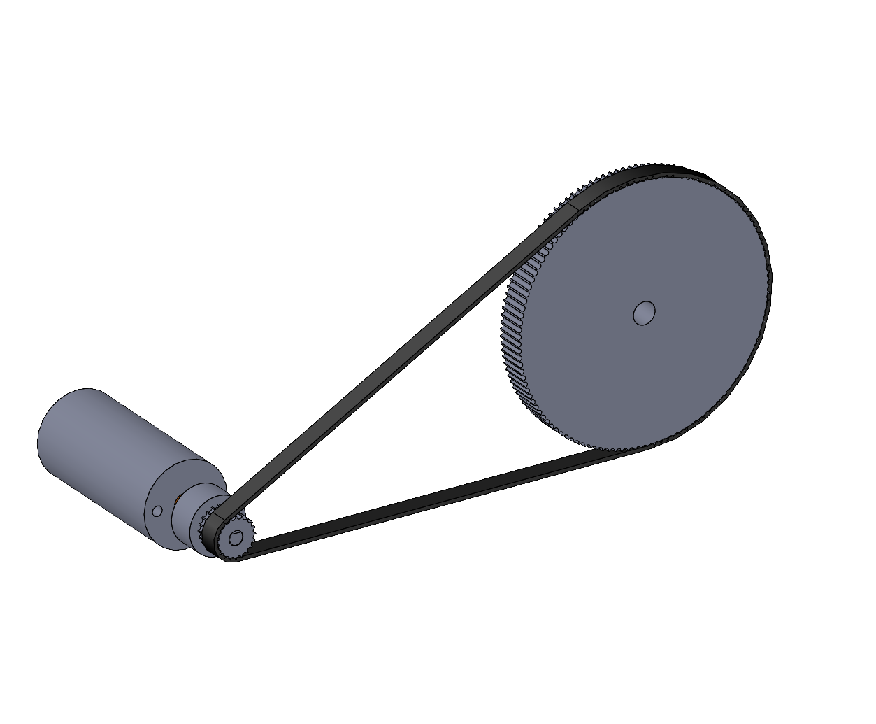
Reduction drive illustration showing a small GT2 timing belt pulley driving a larger one. The actual belts have teeth, but the CAD model shown is simplified and doesn’t include the teeth.
The torque of our small DC motors can be increased using a reduction drive, although at the cost of slower output rotation. A small GT2 pulley with a 4mm bore may be mounted directly on the motor shaft. A larger GT2 pulley can be purchased, laser-cut, or 3D printed. The pulley separation must be designed with a specific length of endless timing belt in mind, please see the calculators listed above. N.B. we stock very few endless belts, but these can be ordered from McMaster-Carr: look for ‘HTD’ belts with 2mm pitch.
Customizable GT2 Pulley
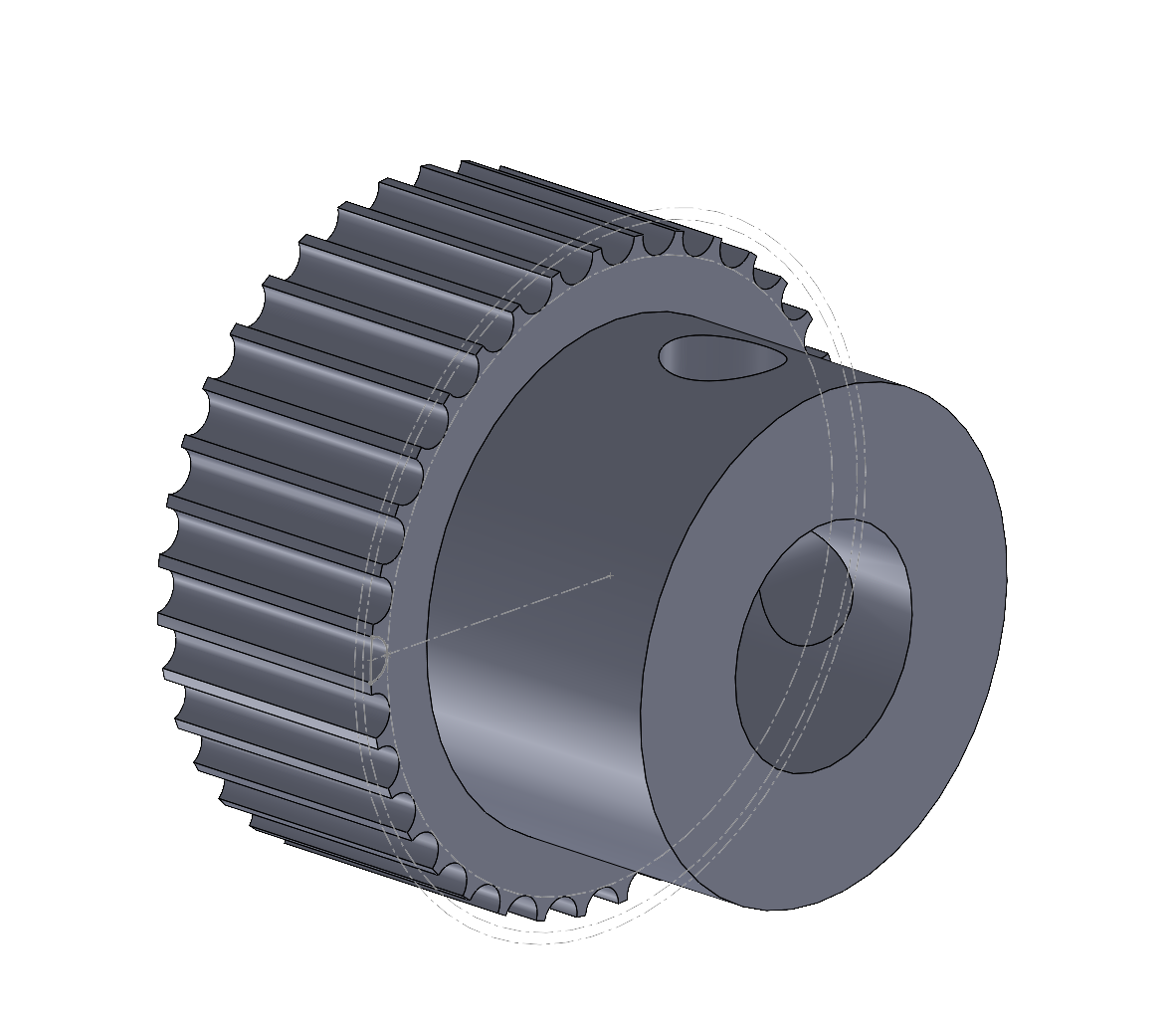
GT2 pulleys may be purchased with a variety of tooth counts, bore sizes, and hub and flange configuration. However, sometimes it solves a design problem to fabricate a custom pulley, either as a 3D-printed part or as a laser-cut tooth profile. For example, it is possible to create large-diameter ring pulleys which are not commercially available.
The GT2-timing-pulley.SLDPRT file is a pulley model designed to be easily customized. It features a design table which generates a large set of standard pulley tooth sizes and which can be easily expanded for any tooth count. It includes optional hub and bore features which can be unsuppressed to customize the shaft interface.
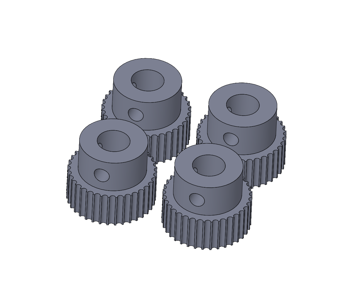
The GT2-pulley-fabrication.SLDASM file demonstrates a convenient way to set up a 3D print job which simultaneously fabricates a complete set of pulleys. All the pulleys can be exported within a single file by enabled the STL options flag “Save all components of an assembly in a single file”.
GT2 Idler Support (3D Printed)
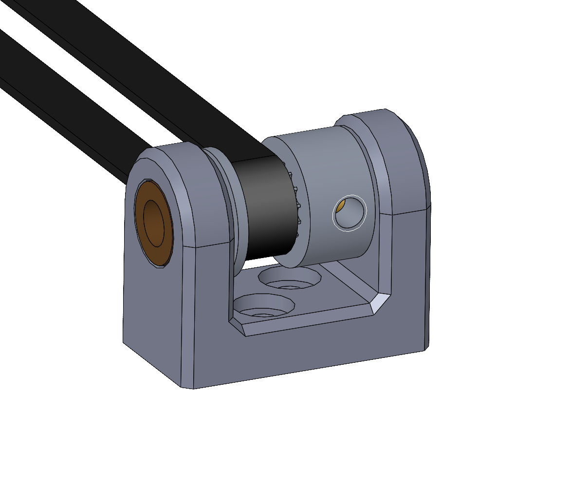
This sample demonstrates a method for supporting a small idler pulley. These are commonly used to redirect a belt. The clevis has holes into which bronze bushings can be pressed, which support a shaft on which the timing pulley is installed.
The typical assembly sequence:
Press the bearings into the clevis.
Install the clevis on the machine structure using two M3 screws.
Hold the pulley in place and insert the dowel pin shaft.
Tighten the pulley setscrew to secure it to the shaft.
Bill of materials:
qty |
description |
|---|---|
1 |
idler clevis, fabricated using 3D printing |
2 |
bronze bushing, 5 mm ID, 9 mm OD, 6 mm W |
1 |
dowel pin, 5 mm OD, 25 to 30 mm long, used as shaft |
1 |
GT2 timing pulley, 16 or 20 teeth, 5 mm ID |
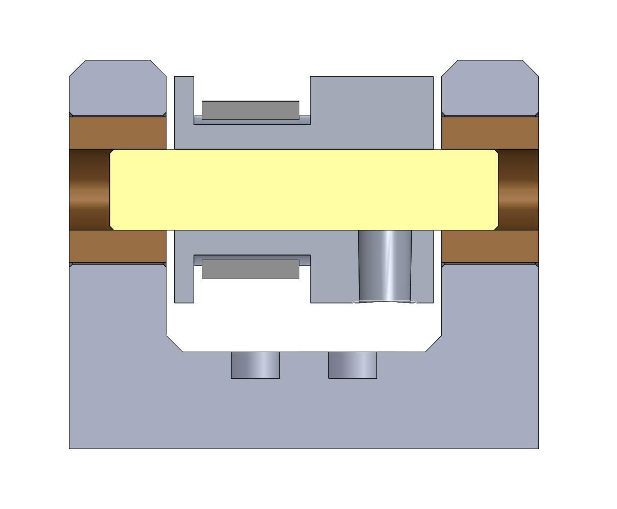
Section view showing the mid-plane of the clevis. The bushings, shaft, pulley, and belt are visible in cross-section. The mounting holes are only partly visible since they are displaced in front and behind the midplane. The timing belt is drawn in simplified form without teeth; in practice the belt teeth engage the pulley teeth.
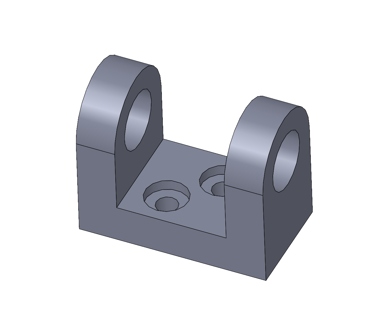
Clevis without bearings, shaft, pulley, or belt.