Exercise: Actuated Marble Run Tile
In this exercise we will design a new marble run tile incorporating a hobby servo actuator. A marble run is a structure in which one or more marbles traverse a course primarily powered by gravitational potential. The actuator can provide energy input by lifting a marble against gravity, control the marble pathway by moving mechanical elements, or both.
The main objective of this exercise is implementing a mechanism using 3D-printed parts. A secondary objective is developing your parametric design skills in 3D CAD. The scope and size of the design idea should be chosen in keeping with your existing CAD skills. If you are a novice to parametric CAD, then please keep your priorities centered on modifying the sample device to suit your creative goals. If you have prior CAD experience, please choose a more ambitious scope.
Please expect that your initial design will include mistakes and plan your time to include fabricating an improved iteration.
Objectives
The overall objective of this exercise is to design and fabricate a single ‘tile’ of a marble run which incorporates a hobby servo actuator. This may be a standalone run or include inputs and outputs so it may be assembled on a sloped table with other active or passive tiles.
The goals of this exercise are that you should be able to:
Conceive and sketch a simple mechanism including ball pathways, moving elements, actuator mounting, and motion transmission.
Create 3D parts from 2D CAD sketches:
that use parametric constraints and dimensions to capture design intent
that support iterative design modification
compatible with the limits of the 3D-printing process
Create multi-part assemblies.
Fabricate, assemble, and test a mechanism combining 3D-printed plastic and standard parts.
Program an open-loop actuator motion to activate a mechanical system.
Preparation
The first rule of mechanical design: work out the idea using paper drawings, paper and cardboard mockups, role play, and hand experimentation. Only after the idea seems workable should you move to CAD.
The first rule of CAD: always make a paper drawing first. The second rule of CAD: always make one more paper drawing before approaching the software.
Sample Parts
The sample files for this exercise can be browsed on the course site:
Or as a single zip file:
Sample files are provided on the assumption that students will go farther given a stronger foundation, so these are provided for you to examine and use as starting points. But if you use one as a template, please be mindful that you add meaningful development, not just tweak it trivially.
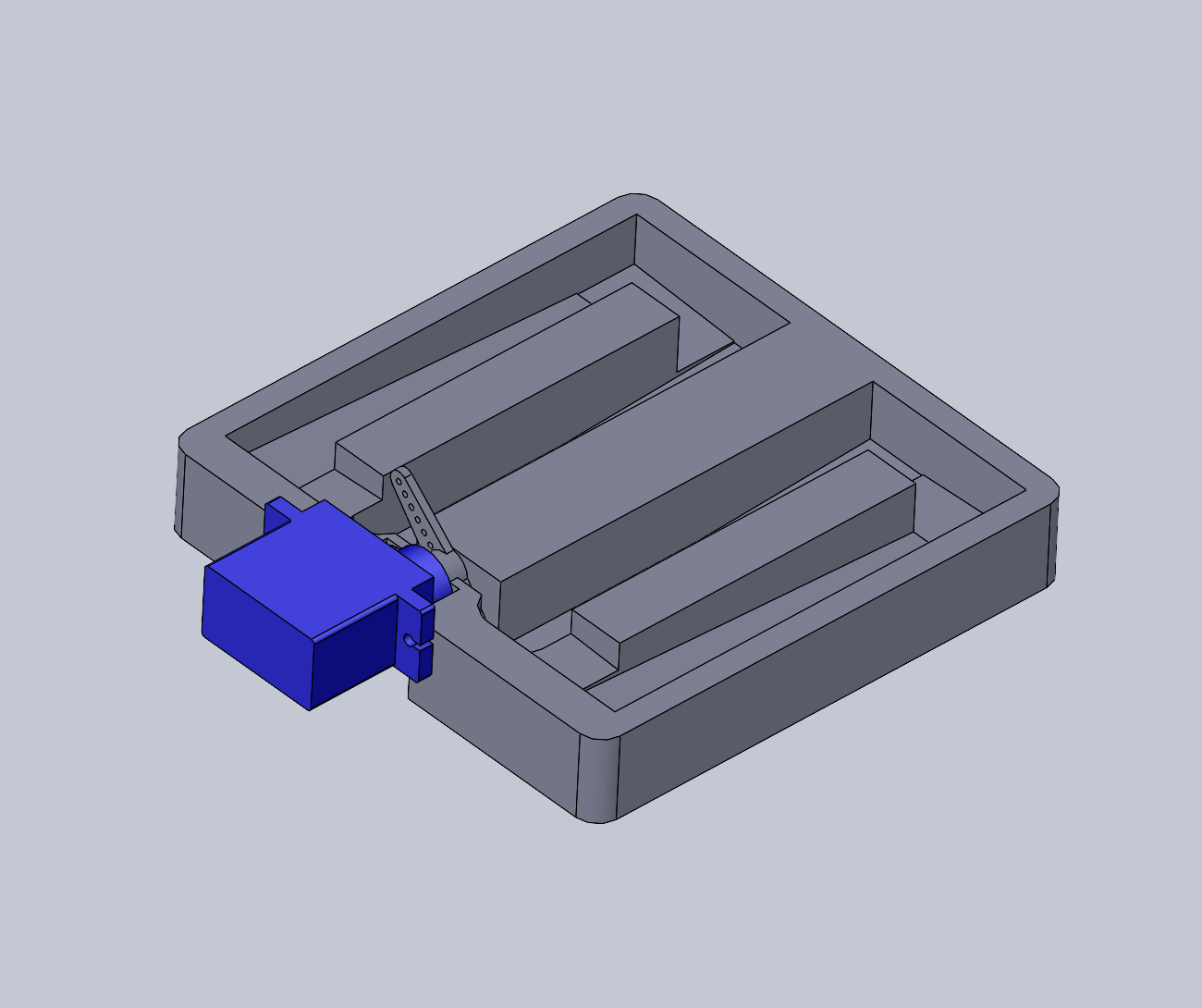
Example of an actuated marble tile. This design is self-contained without entry or exit ports. The lifting arm can directly push balls upward to the top of the track.
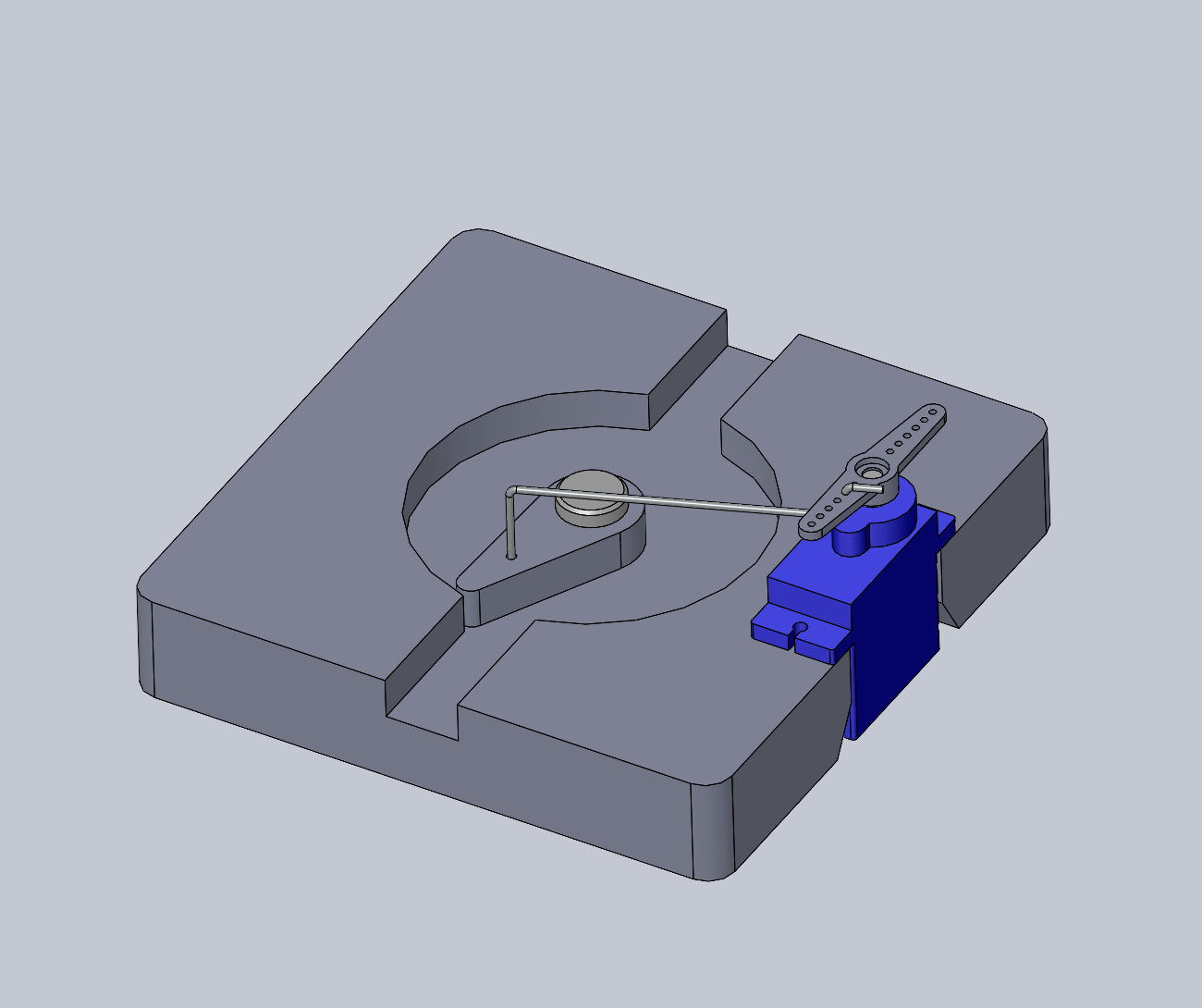
Example of an actuated marble tile. This design acts as a switch to shunt the ball between different pathways. The driver arm is moved by the servo via a wire linkage.

Mounting pattern for the 9G micro servos for use with laser-cut 6 mm plywood. In plywood, the 1 mm holes produce a hole for self-tapping the small wood screws provided with the servos. For 3D printed PLA, 1.9 mm holes are recommended. The 13 x 24 mm rectangular hole provides enough body clearance for the wires to be inserted during assembly.
Material and Tool Constraints
Most of the material and tool constraints are the same as for Exercise: Marble Fidget Toy.
Please fabricate all parts from 3D-printed PLA.
The tile should fit into a 90 mm square. Entry/exit ports should be located at the midpoint of one or more edges.
We will use 3/8 inch steel marbles. A 11 mm track width is recommended for generous clearance. For reference, we also stock 1/4 inch steel marbles, 5/8 inch glass marbles, and a limited supply of standard 27 mm pinballs.
Please follow the hobby servo mounting drawing above.
If driving a mechanism, please use a linkage or other indirect drive. The servo horn is not intended for collisions or heavy masses.
Deliverables
Live in-class demo of your tile.
A short report posted to the course site including:
a zip of your SolidWorks files
a photo and/or brief video
a short text statement reviewing your intent and outcomes
your CircuitPython code posted inline
Challenges
If you would like to explore more, please consider the following optional challenge question:
How would you perform computation mechanically using marbles? The marbles could serve as the power source and data transmission. Information could be stored either by marble location or the position of mechanical elements.
Ideas: