Servo Circuits
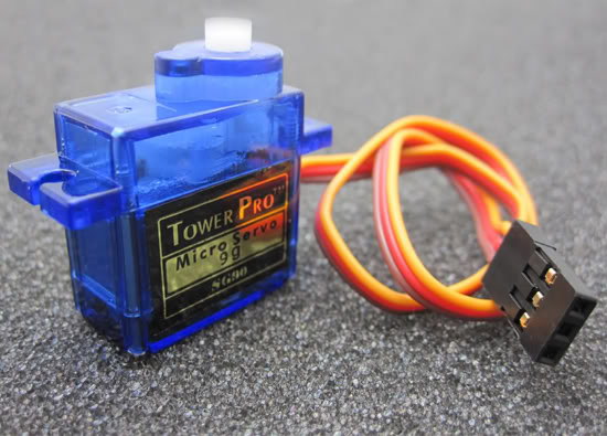
Hobby servos are feedback-controlled motors which move an output shaft to a specified position. They are a very convenient modular way to create controlled physical motion. The circuits involved are usually quite simple, as shown below. The mechanical design and usually requires more consideration, as discussed in the mechanical design guide under Hobby Servos. Programming involves PWM and trajectory generation, as discussed under Hobby Servo Examples - Raspberry Pi Pico.
Pico Servo
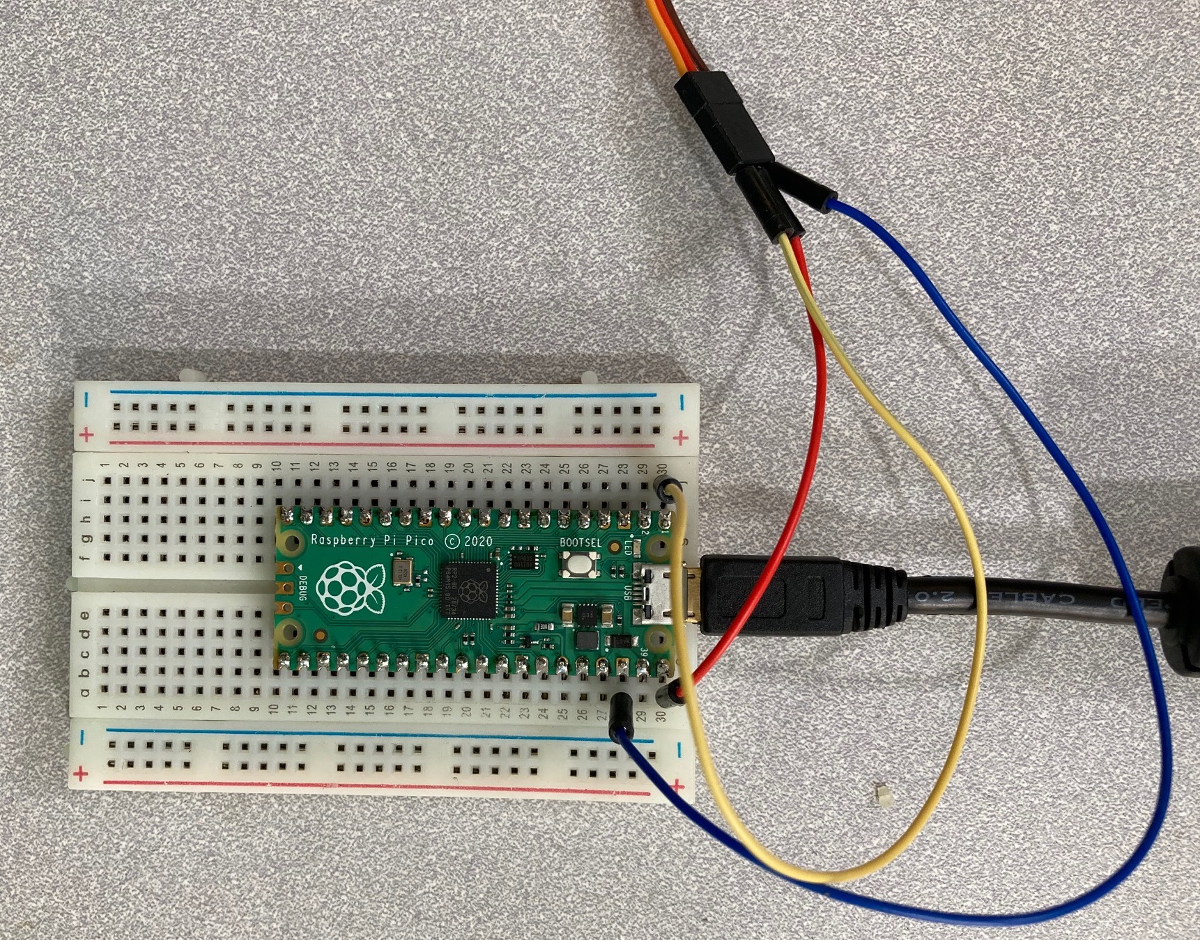
A basic wiring setup for driving a single small hobby servo from a Raspberry Pi Pico. The Pico has header pin row soldered on both sides. The red jumper wire in pin 40 (VBUS) connects the USB +5V to the servo red power input. The blue wire on pin 38 (GND) connects ground to the servo brown ground input. The yellow wire on pin 1 (GP0) connects the control signal to the servo orange signal input. Note that the jumper wire colors themselves are not critical, but consistency helps with recognizing mistakes.
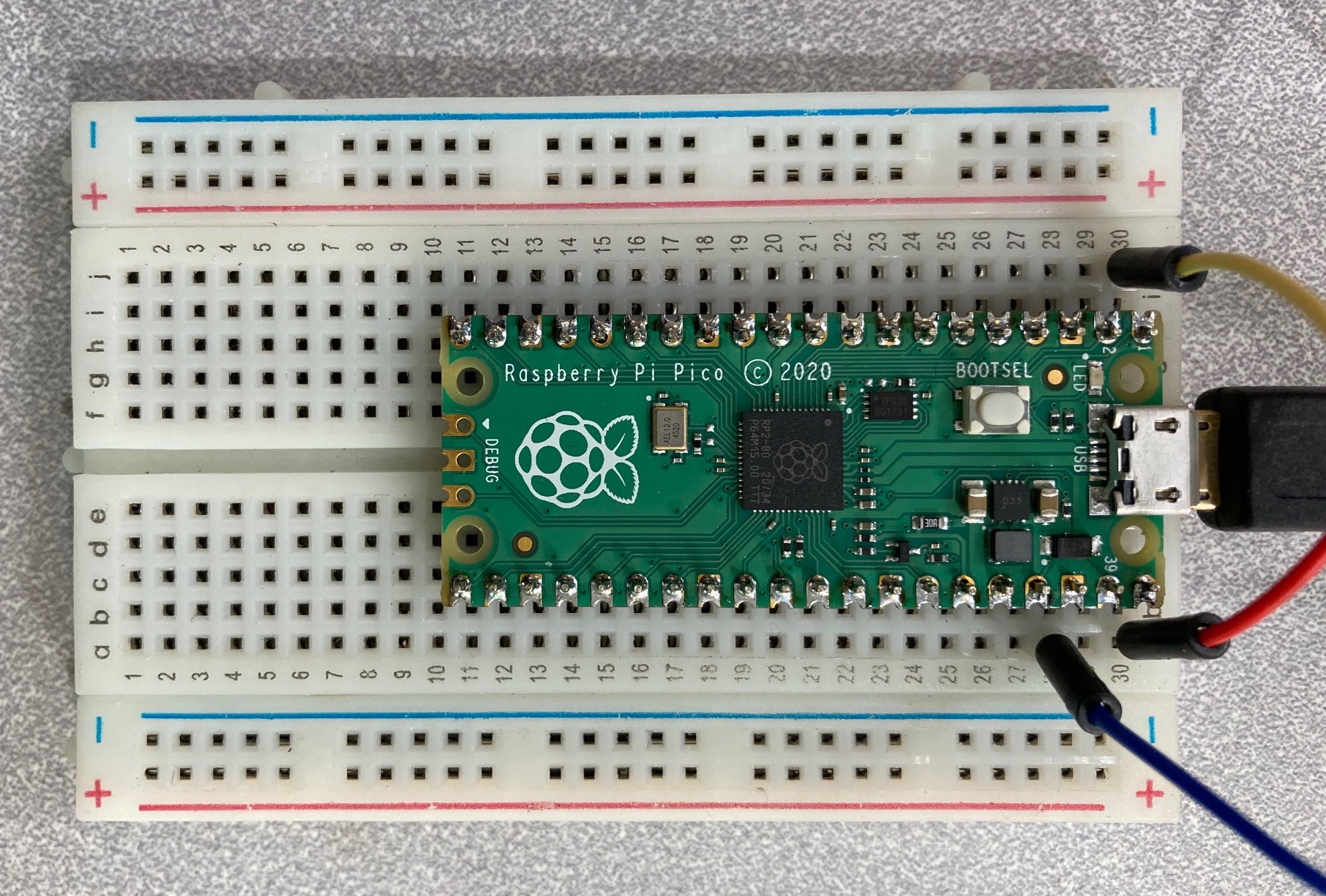
Detail of the jumper wires connecting to the Pico. Each short row of five sockets on the breadboard connect together, so the jumpers wires connect to the adjacent Pico pin.
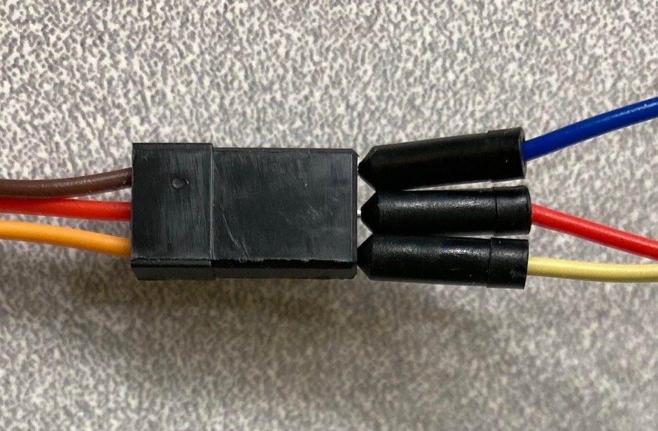
Detail of the jumper wires connecting to the hobby servo. The servo has a female socket header, so the jumpers wires can directly connect, albeit the retention is weak.
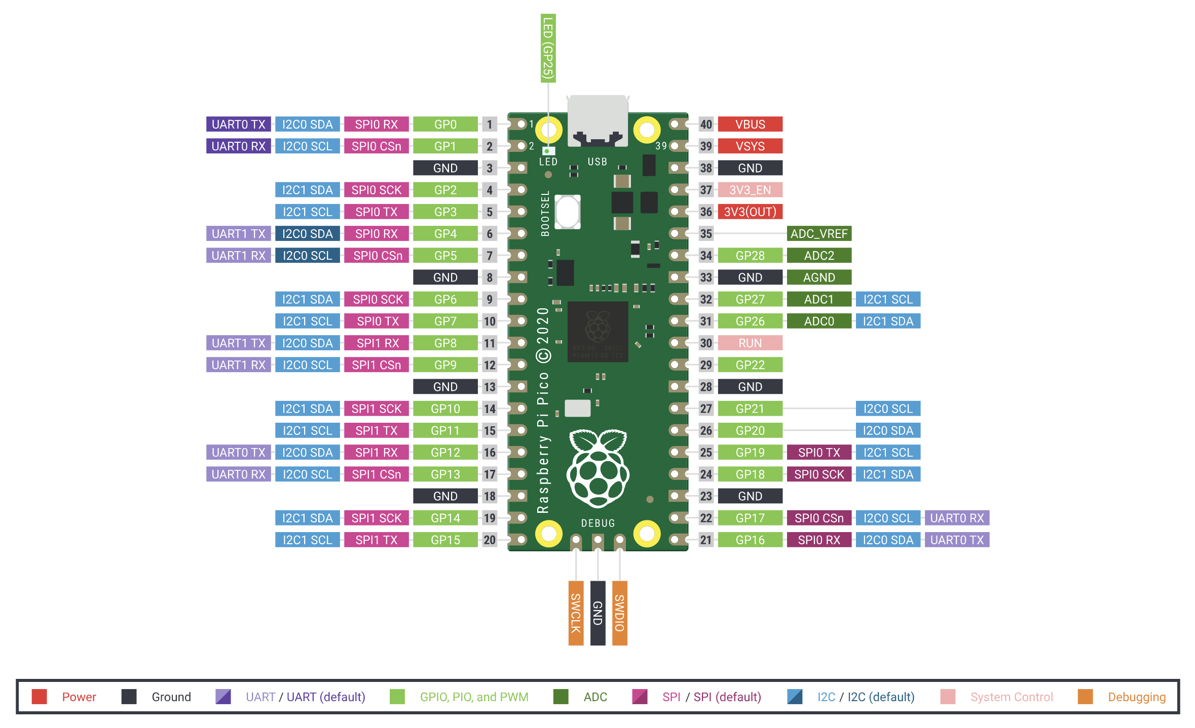
Pin diagram of the Raspberry Pi Pico.
Pico Servo with Photointerrupter
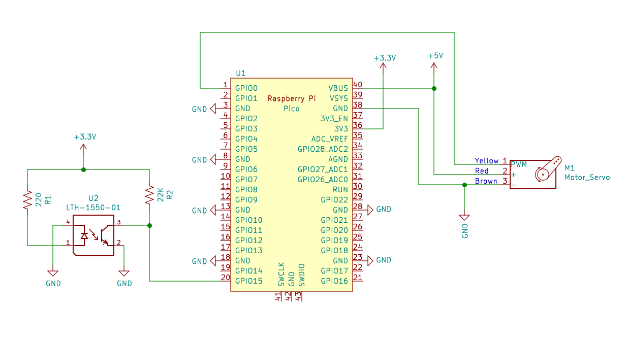
Demo circuit attaching a reflective photointerrupter and a hobby servo to a Raspberry Pi Pico. The photointerrupter must be powered from the 3.3V supply on pin 36 to limit the Pico input voltages. The hobby servo must be powered from the 5V supply on pin 40 for sufficient motor current. The specific GPIO pins match the sample code, but could be changed to any other GPIO pins.
Sample Code
Sample code for reading a digital input: Digital Input/Output Examples - Raspberry Pi Pico.
Sample code for driving a servo output: Hobby Servo Examples - Raspberry Pi Pico.