Actuators
An actuator is a component which transduces energy into motion. Our basic actuators include electric motors, hobby servos, stepper motors, and solenoids. The term generally implies that the motion is controlled in some way, even if just to cycle on and off. So in contrast, a constantly-powered DC motor is an actuator with a constant input but it is more useful to classify it as a mechanical power source.
A speaker is technically an actuator, but since the emphasis is on producing audible vibrations we’ll consider it as a separate category. A pneumatic cylinder is an example of an actuator which transduces the energy of compressed air into movement, and they are frequently controlled by valves which use a solenoid as an actuator to control fluid valves.
More details on our typical parts can be found on Lab Inventory: Actuators, Motor Mounting, and Hobby Servo Mounting.
Gearmotors
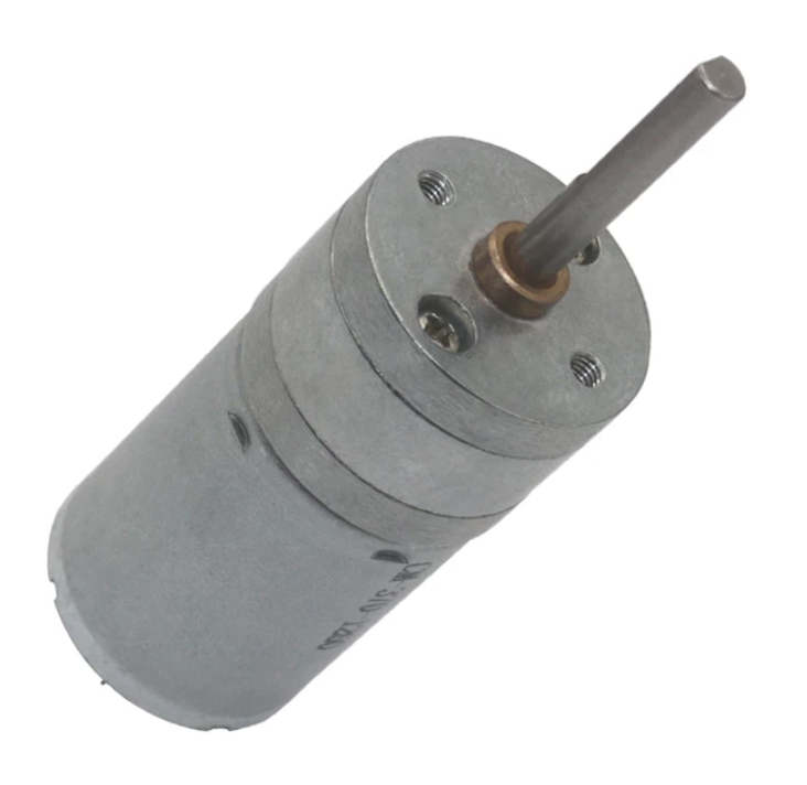
A gearmotor is an actuator which converts electricity into rotary motion using the combination of a DC motor and gearbox to reduce speed and increase torque.
Our basic kit part is Lab Part 1931, a 25 mm diameter gearmotor which operates on 5 to 6 Volts. For bidirectional motion the recommended driver circuit uses a TB6612FNG (Lab Part 0485). For single-direction drive a single MOSFET circuit is sufficient (e.g. using a IRLB8721PbF Lab Part 8721).
For more details on physically attaching motors into your project, please see Motor Mounting.
Hobby Servos
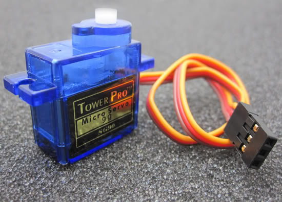
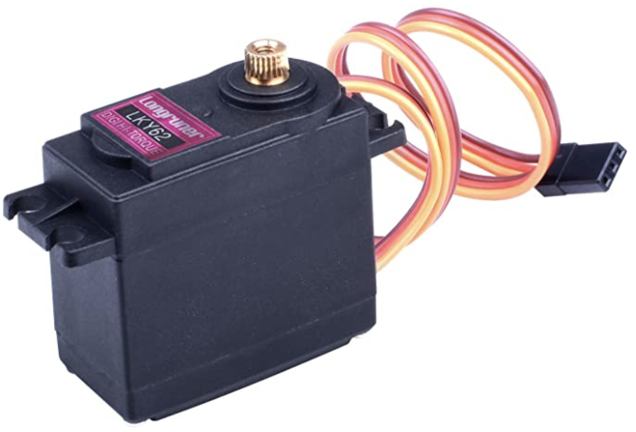
Hobby servos are feedback-controlled motors which move an output shaft to a specified position. They are a very convenient modular way to create controlled physical motion.
Internally they use a potentiometer to measure the actual position. The internal circuit compares the actual and commanded position and generates positive and negative motor current pulses to operate a tiny gearmotor. The typical range of travel is 180 degrees, although specific servos may allow some travel beyond those bounds. Other specialized types of servos support multiple turns or continuous rotation.
For details of our specific lab stock please see Hobby Servos.
Mechanical Considerations
Hobby servos frequently have a rectangular case with protruding mounting tabs. It is possible to directly clamp the case, but the recommended mounting is always to use the tabs and supplied screws. This often leads to a panel mounting scheme with a rectangular clearance hole for the body and small pilot holes to accept the screws. For more details on physically attaching hobby servos into your project, please see Hobby Servo Mounting.
Hobby servos typically have a splined output shaft with grooves for strong torque transmission. For this reason, it is only practical to use them with the supplied servo horns which are molded to fit the spline shaft.
The output shaft is designed to transmit torque and support limited radial loads, but isn’t suitable for carrying large overhung loads. In general, it is poor practice to mount wheels or heavy masses directly to a servo horn. Rather, the bulk loads should be separately supported by bearings and the servo coupled to the load using wire links. This separates out the unactuated axes and limits the servo horn forces to pure radial loads and pure on-axis moments.
Electrical and Control Considerations
The commanded position is specified using a specific format of pulse-width modulation (PWM) in which pulses with duration approximately 1-2 ms repeat at approximately 50 Hz. The different pulse widths correspond to different positions. Note that this a significantly different waveform than the motor PWM, since the duty cycle is always very low, i.e., the pulse on-time is always much shorter than the cycle time. The PWM in this case is used to encode the target motor angle information instead of delivering energy.
Please note that the feedback signal is internal to the servo and not easily available. For this reason, we consider hobby servos as output-only devices without axis position feedback. In practice, hobby servos are speed-limited so the actual position will lag the commands. They also typically have a small ‘deadband’ in which the small errors won’t produce motion; this is a means to reduce chatter in which the servo oscillates around the target.
The small hobby servos we use are designed for use in toys and model airplanes. As a result, they are engineered to tolerate a range of power supply voltages since they are often powered by batteries. Our typical micro-servos can tolerate from 3 to 6 VDC input and we generally operate them at 5 VDC. A single micro-servo has a low enough power consumption to safely operate off USB power, but please note that multiple micro-servos or larger servos can easily draw more than 500 mA and so use of an external power supply is required.
There are several wiring schemes found on hobby servos, but the micro-servos we use follow the following three-pin “JR” convention on a female connector with 0.1” spacing:
Brown
Ground
Red
Supply Power
Orange
PWM Control
However, there are other schemes including “Futaba” and “Hitec” in which both the colors and pin order are different, so please always research your specific part.
For wiring and circuit examples, please see Servo Circuits.
References
Stepper Motors
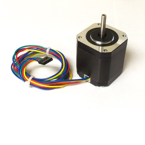
A stepper motor is a rotary electric actuator which moves in discrete angular steps. A major benefit of a stepper motor is precise control of rotational position without needing a sensor component or circuit for feedback.
Internally, the rotor has teeth which provide magnetic detent positions relative to the magnetic field produced in a stator by a pair of windings. If the motor is overloaded, the magnetic field detent is overcome, so it can slip and lose position but no mechanical parts will break.
Lab Part 1908 is a standard NEMA17 size, 200 steps per revolution, and uses a 5 mm diameter shaft. It has two windings and requires a specialized driver like the A4988 (Lab Part 4988) to operate. This driver can use current control to divide each step into as many as 16 smaller microsteps, for a total of 3200 positions per revolution.
For more details on physically attaching motors into your project, please see Motor Mounting.