4.9. Basic Motoman SDA10D Operation
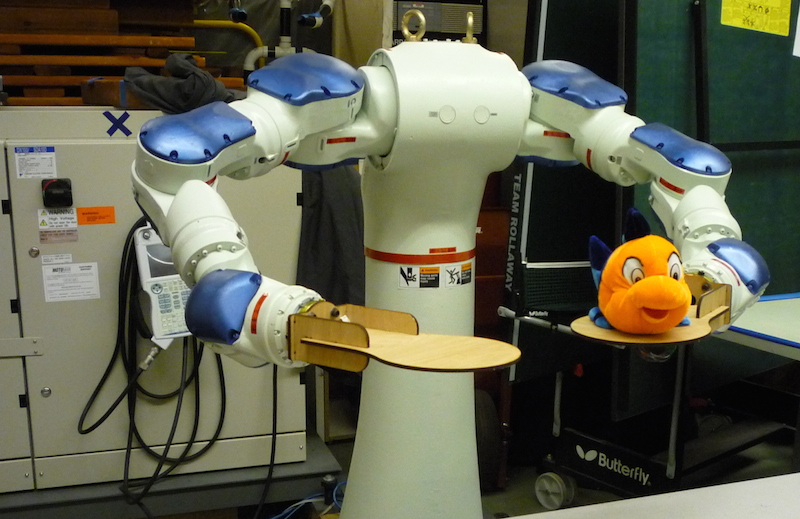
The Motoman SDA10D is a dual-arm manipulator located within the Motion Capture Lab in Wean 1334. It is owned by Prof. Nancy Pollard, who has graciously agreed to let us borrow it for an exercise.
Please do not attempt to operate the robot on your own unless you have been personally trained by your instructor. It is a expensive and dangerous tool and we’d like to ensure safety for both you and the equipment.
Contents
4.9.1. Getting Started
- The main power switch is located on the front of the cabinet. Turn the handle to vertical “ON”.
- The controller will take several minutes to boot up. The teach pendant will show various boot status messages.
- Remove the teach pendant from the hook on the front of the machine and carefully unwind enough cable to stand at a safe distance. Please be mindful and never step on the teach pendant cable.
4.9.2. Essential Teach Pendant Controls
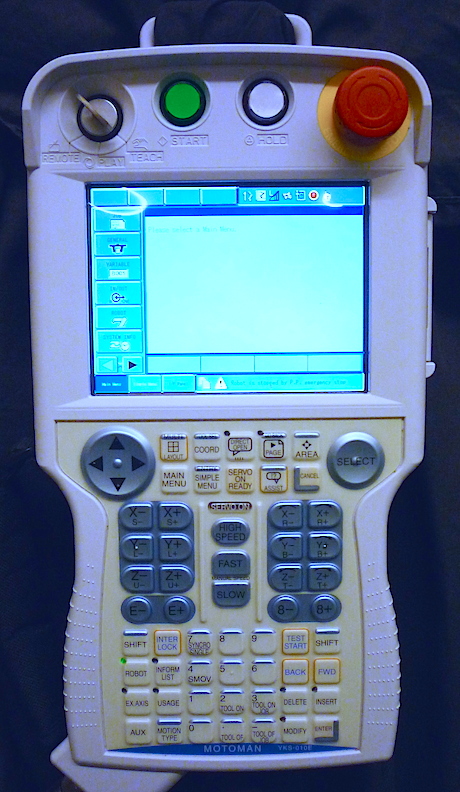
EMERGENCY STOP. This should really be called the ‘safety switch’ as we routinely press it whenever we need to guarantee the motor power will stay off. Twist clockwise to release.
Mode Switch. This key switch selects between Remote, Play, and Teach. Teach is used for driving the robot to locations and recording way points. Play is used for running jobs without intervention in conjuction with the adjacent START and HOLD. We will not use Remote.
Enable Switch. This is a deadman’s switch located on the back of the pendant under your left fingers. It must be held down lightly during teaching operations and is designed for instant release in the event of a problem. Squeezing hard will also turn off the power, e.g. if you are tensing up after being struck in the head by a robot.
Touch screen. The screen is touch-sensitive and many menu controls can be activated directly.
SELECT and cursor arrow pad. Most menu functions can also work by scrolling between items with the arrows and pressing Select.
SERVO ON READY. In teach mode, this enables the motor power system. Subsequently activating the enable switch will cause the motors to turn on and the brakes to release. When the servos are enabled the SERVO ON flashes green.
ROBOT. The SDA10D is operated as three logical robots: R1 is the left arm, R2 is the right arm, and S1 is the torso (the station, also the first external axis.) The ROBOT button cycles between controlling R1 and R2. The EX. AXIS button switches to controlling the torso. The pendant can only directly control one subsystem at a time.
HIGH SPEED, FAST, SLOW. These control the jog speed during teaching. The very slowest speed moves only one encoder tick at a time which is essentially imperceptible. The fastest speed can be quick, please be careful.
COORD. This selects the active coordinate system when driving a robot. The mode cycles between joint coordinates, Cartesian coordinates, tool coordinates, and user work coordinates. This changes the meaning of the axis keys.
Axis keys. There are sixteen buttons devoted to driving the robot, of which we use fourteen (8- and 8+ have no function for us). Each button comes in a plus/minus pair and controls either one joint angle or one Cartesian coordinate. The arm axes are named with letters which appear in the following kinematic sequence from shoulder to wrist: S,L,E,U,R,B,T. Note however that the E-/E+ buttons appear out of sequence. The left XYZ buttons are used in Cartesian mode for positioning, and the right XYZ buttons are used for rotations. In Cartesian mode, the E-/E+ buttons control the redundant freedoms within the arm which can move without the end effector changing position.
There are a number of other controls, all documented in detail in Section 1.2 of the Operator’s Manual.
4.9.3. Driving the Robot
- Note the first few icons in the right half of the top row of the screen: the active robot indicator, the active coordinate indicator, and the job speed (looks like a bar graph). These are defined in more detail in section 1.2.4 of the operator’s manual.
- Make sure the mode switch (key switch) is set to Teach.
- Use the ROBOT or EX. AXIS buttons to select which subsystem to control. R1 is the left arm, R2 is the right arm, S1 is the torso.
- Use the COORD button to select the active coordinate system. You will generally only need joint coordinates and Cartesian coordinates at first.
- Use the FAST and SLOW buttons to select a jog speed. If the robot isn’t too close to anything, Medium is reasonable for basic driving.
- Release the emergency stop if needed.
- Press the SERVO ON READY button to enable the servo system. The SERVO ON light will begin to flash green.
- Use the fingers of your left hand to depress the rear enable switch. You should hear the brakes release and the high-pitched whine of the servo motors.
- Choose a direction in which to move. When in Cartesian mode, X+ is ‘forward’, Y+ is to the ‘left’, Z+ is ‘up’, all when viewed from the perspective of the robot. (E.g. the long axis of the Mocap lab is X+, the controller of the robot is behind it and a little to the right in X-,Y-.)
- Press and hold the appropriate axis key to move. Cartesian mode is easier to visualize at first, it takes a little time to become familiar with the action and each direction of each joint.
- Multiple keys can be held at once for ‘diagonal’ motions.
- The coordinate system, robot, and speed can all be changed without releasing the motor enable.
- Whenever you need to move within physical distance of the robot, release the enable switch and also press the emergency stop switch to cut off all chance of power.
- The robot has no limits against self-collision. Please use caution when the arms are close to each other or the body. The robot also has no limits against world collisions, so please be mindful of the furniture.
- The robot joints will not extend past their individual limits.
- Pressing and holding HIGH SPEED will temporarily use a very fast jogging rate. Please only do this when the robot is comfortably clear of all obstacles and self-collisions.
4.9.4. Teaching a Sequence
- Create a new empty job file with the following sequence of selections: Main Menu, Job, Create New Job, select Job Name, enter a name on the on-screen keyboard, on-screen Enter, select Group Set, arrow key and Select to indicate active subsystems (R1R2S1S* for full 15-axis control), leave Job Type as Robot Job, press on-screen Execute.
- Drive the robot to the first pose using the driving controls as described above.
- Press the ENTER button at the lower-right corner of the keypad to insert a new pose. You should hear a beep and see a new line inserted in the program on the screen. The default move type for dual-arm control is ‘MOVJ +MOVJ’ which will perform joint-space interpolation on two arms simultaneously. (There are also several other options available in the INFORM language; see the INFORM Programming Manual for details.)
- Record several poses by following this jog/insert cycle.
- To single-step through a pose sequence, move the cursor to the desired program start position with the arrow keys, then press and hold the FWD button. The robot will move from its current location to the desired pose. Each subsequent press and hold will advance to the next pose. The BACK button is similar but moves to the previous position. Please be careful when jumping into the program, since the robot will move directly to a pose which may or may not represent a feasible path.
- To run a pose sequence without a pause, press and hold INTERLOCK followed by pressing and holding TEST START. (INTERLOCK may be released once TEST START is pressed.) The robot will move at jogging speed through all poses in the program while TEST START is held down.
4.9.5. Running a Job
Once your job has been thoroughly tested in teach mode, it can be run as follows.
- Move the mode switch (key switch) to Play.
- Release the emergency stop.
- Press SERVO ON READY. Note that the motors will immediately power up even without the deadman’s switch.
- Press the green START button at the top of the pendant to run the job.
- The robot will run one cycle of the motion. It may be paused by pressing HOLD. Press START to resume from a hold.
4.9.6. Shutdown
- Drive the robot to a convenient pose where it isn’t at risk of being bumped.
- Turn off the main power switch.
4.9.7. Not Covered in this Tutorial
- Selecting and manipulating job files.
- Setting motion speeds.
- Setting motion interpolation.
- Editing job files on-screen.
- Looping.
- Saving job files via FTP or USB stick.
- (And many other features omitted, see the SDA10D and INFORM manuals.)