6.2. CNC Arduino Shield
We will be using the grbl Arduino firmware for the early exercises in the course utilizing stepper motor drivers. We will use a Protoneer CNC Shield to connect three Pololu A4988 stepper motor drivers to an Arduino Uno. Additional hardware information can be found on the 16-375 datasheets page.
Contents
6.2.1. Arduino Installation
The CNC Shield should be installed on an Arduino Uno as shown in the following image:
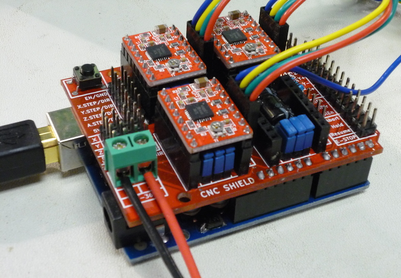
CNC Shield board installed on top of an Arduino Uno.
Note that the shield board has four fewer pins than socket positions on the Arduino; be sure that A4, A5, D0, and D1 are connected and the board outlines line up.
6.2.2. Jumpers
The default jumper configuration for the CNC shield includes all three jumpers
installed underneath each driver module. This pulls MS1, MS2, and
MS3 all high for full 1/16-step microstepping resolution. This trades off
top speed for positional accuracy. If the application requires higher speed,
jumpers may be removed; see the Pololu A4988 product page for details.
6.2.3. Driver Installation
The drivers should be installed in the locations and orientations as shown in the following image:
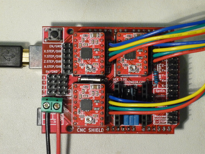
Top view of CNC Shield showing USB cable, power leads, A4988 drivers, and motor leads.
Please carefully note the polarity of the motor supply wiring at the lower left of the image; these should be connected to a 12V power supply.
The colored wires to the right are the stepper motor leads for the KL17H248-15-4A. Either connector orientation works, although this particular orientation is recommended for consistency, with blue toward the top.
Note that each driver has a potentiometer adjustment for the current limit; this must be set as described below.
6.2.4. Current Limiting
The A4988 actively limits the current flowing through each stepper motor coil according to the setting of the current limit potentiometer and the active microstepping phase. This allows a supply voltage substantially higher than the rated motor voltage, increasing step rate performance.
The current limit must be set correctly for the particular motor installed on the driver. It is most easily configured by measuring the voltage on the wiper of each reference potentiometer while using a tiny screwdriver to adjust it. The wiper pin is in the center of the edge located toward the inside of the board. The 5V logic power must applied to the CNC shield, normally by making sure the Arduino is powered via USB. The correct reference voltage is as follows:
VREF = I_max / 2.5
For example, the preferred KL17H248-15-4A NEMA17 stepper motor has a rated
current of 1.5 A, so the correct VREF = 1.5A / 2.5 = 0.6V.
6.2.5. NEMA17 Stepper Motor
We are using the KL17H248-15-4A NEMA17 stepper motor with the CNC Shield. This is a bipolar 200 counts/rev 1.5A/phase stepper motor in a square NEMA17 package. The shaft is 5 mm diameter with a flat, the mounting screws are M3 located on a 31 mm square.
Drawing: cnc-images/KL17H248-15-4A.pdf
6.2.6. Arduino Pin Assignments
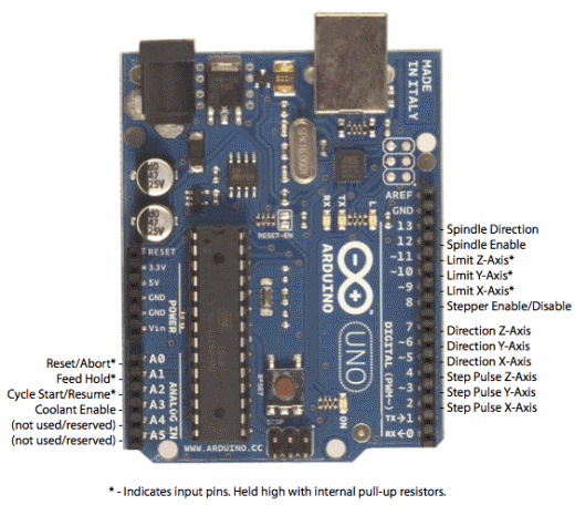
Top view of Arduino with pin definitions labeled.
6.2.7. CNC Shield Circuit Diagram
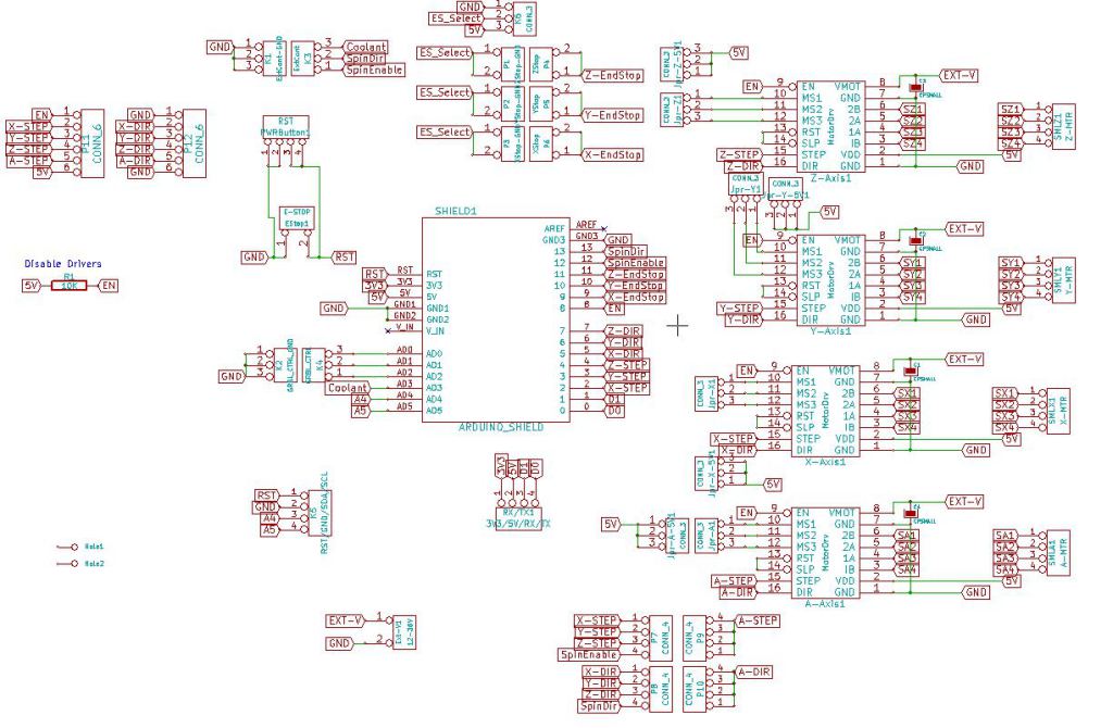
Electronic schematic of CNC Shield board.
6.2.8. CNC Shield Component Layout
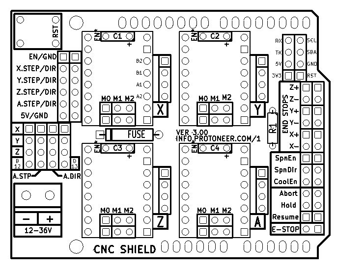
Top silkscreen of CNC Shield board.