6.1. Joint Feedback Setup
We can implement closed-loop control by installing potentiometers to measure joint angles and then applying feedback using software on the Arduinos which control the pneumatic valves. The following documentation will help with setting up the feedback hardware. For software, see ValveControl Arduino Sketch.
6.1.1. Potentiometer
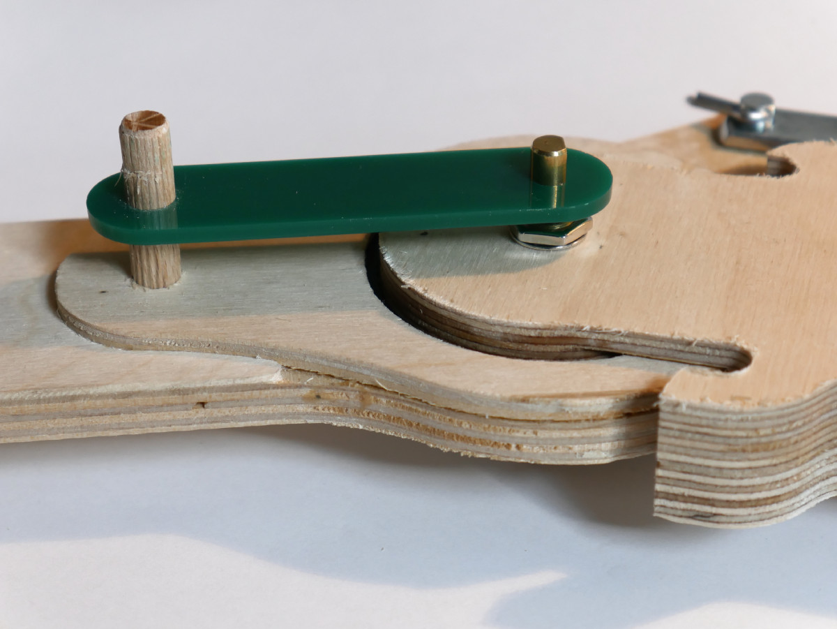
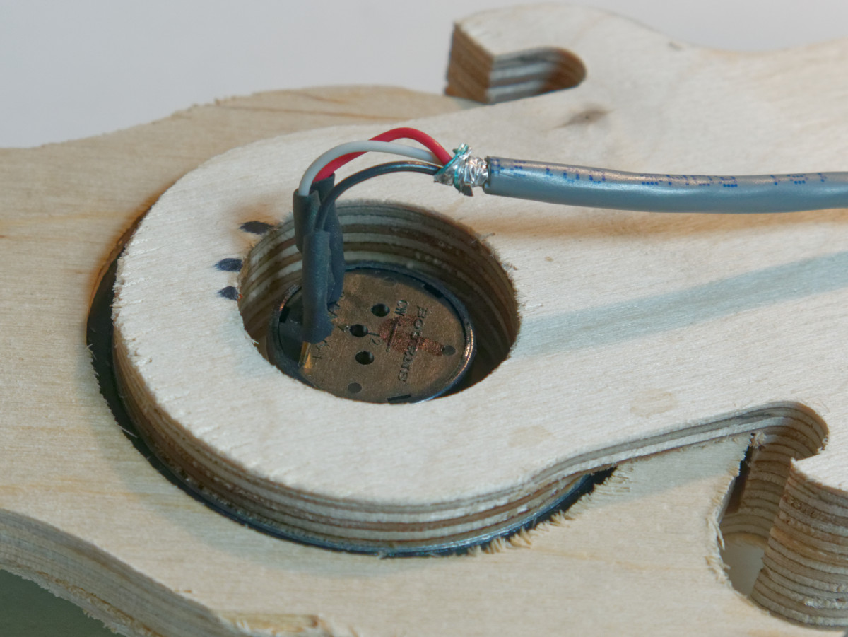
The following images show a potentiometer installed on a knee joint. The body of the potentiometer is installed in the center of the joint link which holds the inner bearing race. The green plastic link connects the potentiometer shaft to the opposite side of the joint. The red wire is +5V, black is ground, and the white is the wiper. The potentiometers we are using are Bourns 6630S0D-C28-A102 1K precision potentiometers.
During installation, it is important to use a multimeter to measure the wiper resistance and position the body of the pot such that it is centered (e.g. 500 ohms) when the joint is at mid-travel. Each joint must be individually calibrated, so the precise offset and scale will be adjusted during software setup and testing.
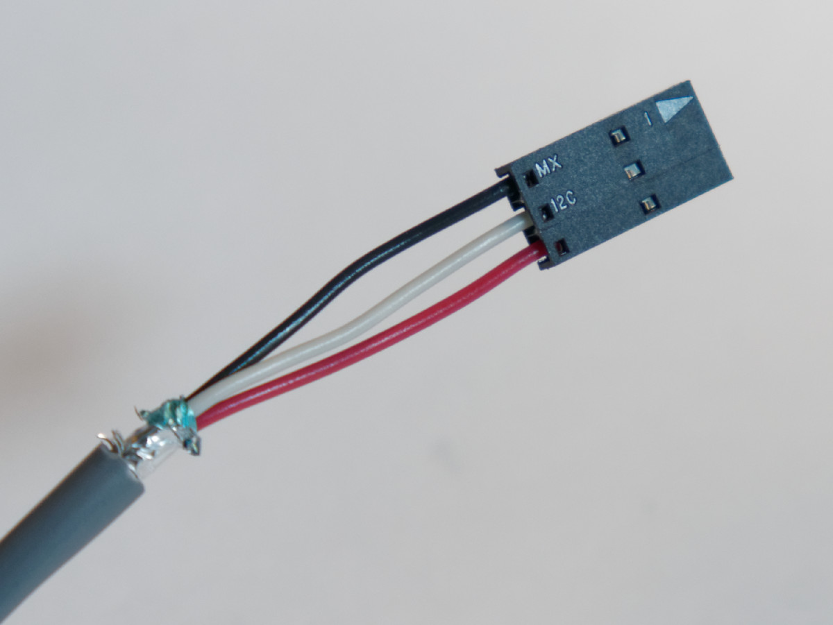
The wires soldered to potentiometer are a three-wire cable, Belden 9533-060100. The opposite ends are crimped into Molex 16-02-0102 terminals and inserted into a Molex 50-57-9003 housing.
6.1.2. Driver Board Wiring
The valve driver board is a Numato Lab ULN2803 driver shield. The connectors for both the valves and the potentiometers are soldered to the prototyping area and connections made using point to point wiring.
Note that both the valves and the pots use three-pin housings, so care is required no to plug them into the wrong pins.
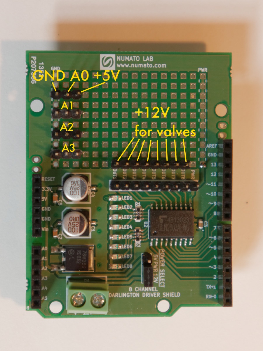
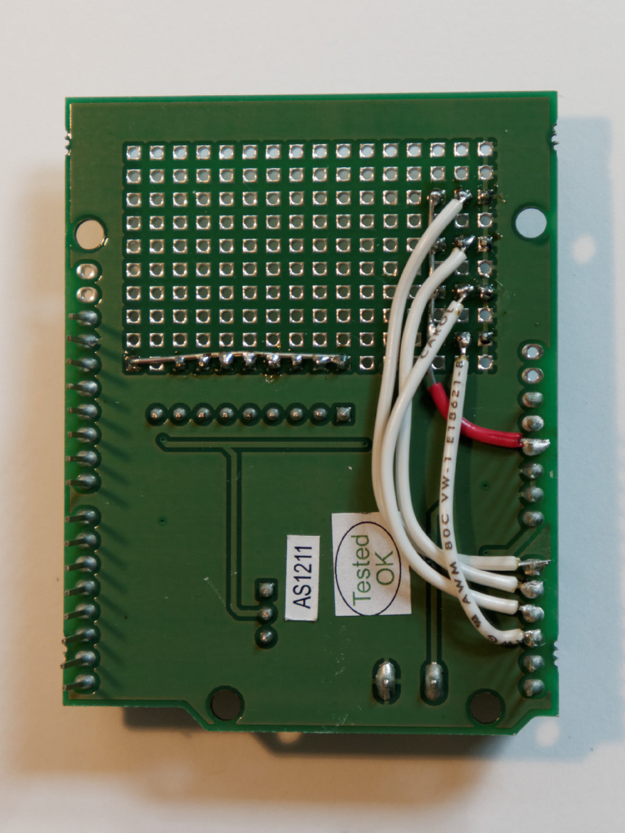
The three pin connectors at the upper left are for the potentiometers. The leftmost row of prototyping area holes are GND; the center pins are wired to A0, A1, A2, and A3. Note that the wires must be closely soldered at the base of the Arduino pins, and the pins kept clean of solder so they may still insert properly into the Arduino.
The row of eight pins adjacent to the normal output poins are wired to +12V; the valves use a three-pin header with the center position unused, and each span one +12V pin and one output pin.