Impeller Testbeds
The impeller testbeds use the same four-channel stepper-motor actuation system as the Suitcase Testbed, but in a more open-ended form factor and with a larger top surface.
Electronics
The electronics use an Arduino with a CNC Shield on top incorporating four A4988 stepper motor drivers. Documentation can be found at CNC Arduino Shield.
A recommended approach for programming the system is to write control scripts in Python which communicate over USB with Arduino firmware which moves the motors.
We are currently using StepperSpline Arduino Sketch for the firmware.
Impeller Testbed 1
The first version uses a square top. The SolidWorks model is available impeller-test-1.zip, or may be browsed as individual files in the impeller-test-1 folder.
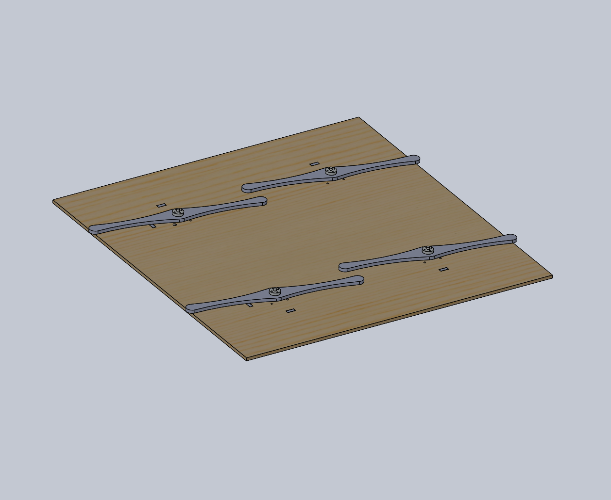
CAD rendering of the Impeller Testbed 1 wooden structure. Four stepper motors are mounted in the deck with hubs installed on their vertically aligned shafts. The electronics and power supply are mounted below the deck.
Impeller Testbed 2
The second version uses a round top. The SolidWorks model is available impeller-test-2.zip, or may be browsed as individual files in the impeller-test-2 folder.
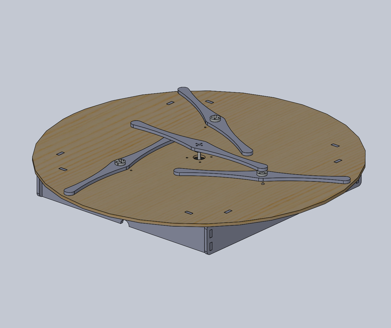
CAD rendering of the Impeller Testbed 2 wooden structure. Four stepper motors are mounted in the deck with hubs installed on their vertically aligned shafts. The electronics and power supply are mounted below the deck.
Accessories
Following are additional parts which may prove useful to experimenting with the impeller testbeds.
Vertical Rotor
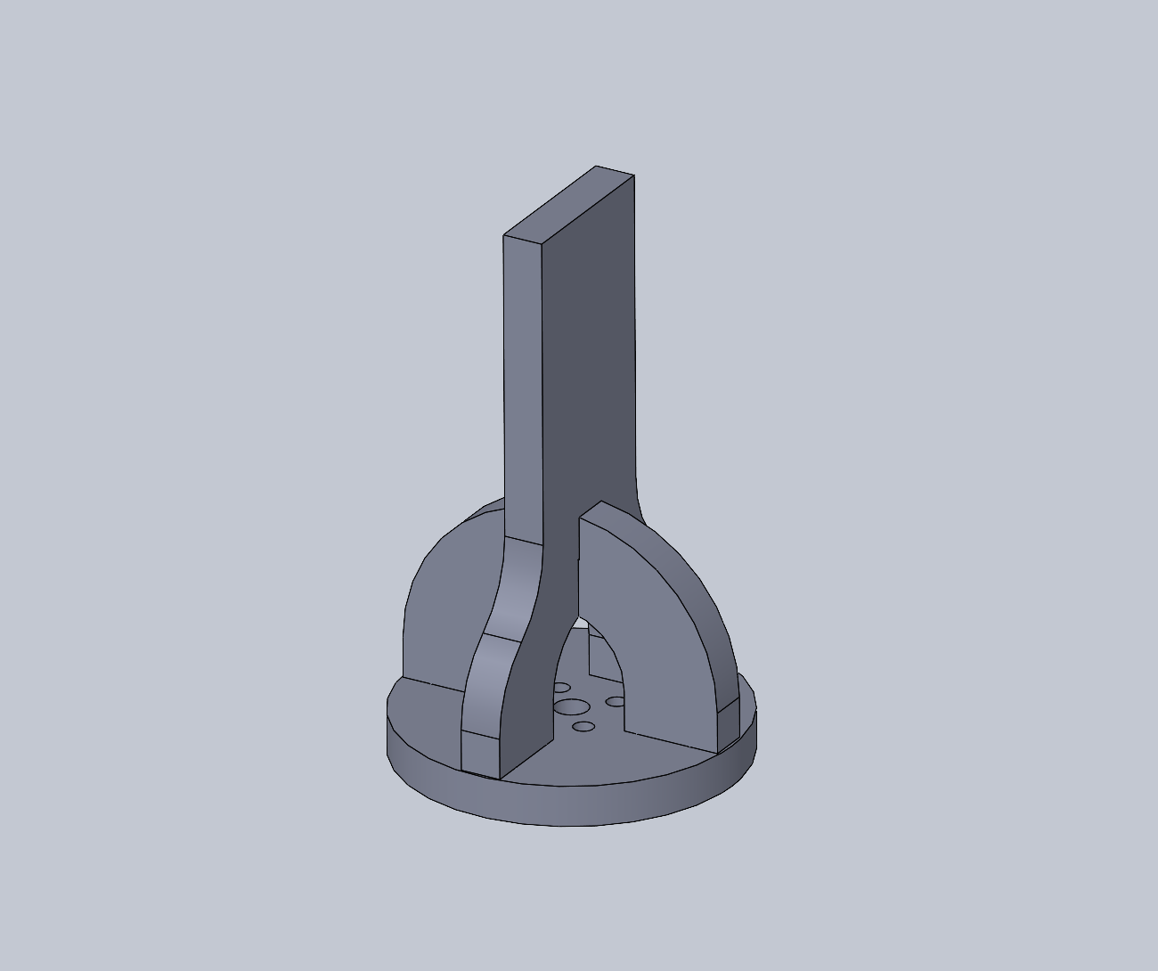
CAD rendering of the laser-cut plywood base-and-post vertical rotor structure. The round base plate may be screwed to a motor hub with M3x10 screws. The brace tabs into two base slots and has a half-slot slot to support the vertical post. This template could be extended to support somewhat taller and larger rotating structures. The stepper motor shaft and bearings are supporting the full load, so some care should be exercised not to exceed strength limits.
CAD files for these parts may be browsed in the impeller-objects folder.
Corner Clips
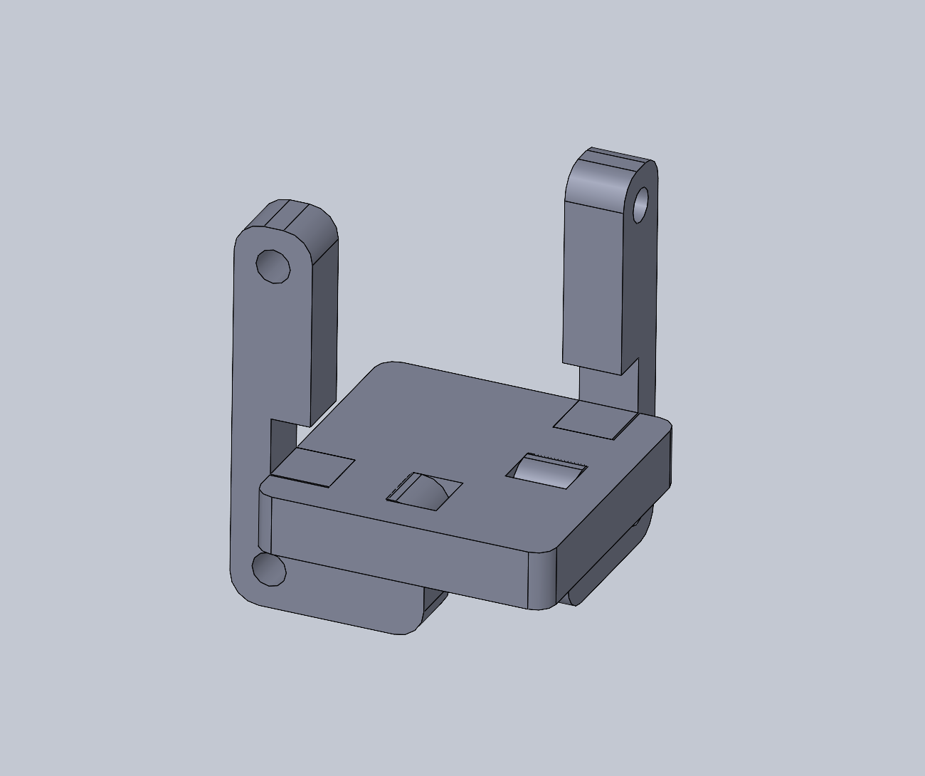
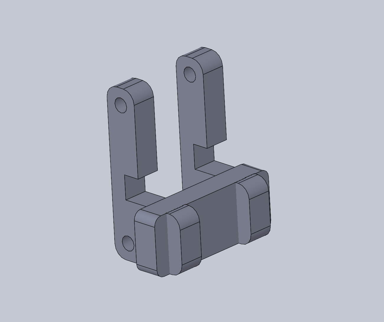
CAD rendering of a laser-cut plywood bracket to fit on the square corners of the impeller-test-1 table. This may be useful for supporting elastic material at the edge without modifying the deck.
CAD files for these parts may be browsed in the impeller-test-1 folder as edge-rib.SLDPRT, edge-corner-strut.SLDPRT, and edge-corner-brace.SLDASM.
Edge Clips
CAD rendering of a laser-cut plywood bracket to fit on the round edge of the impeller-test-2 table. This may be useful for supporting elastic material at the edge without modifying the deck. The rib parts are identical to the corner brace.
CAD files for these parts may be browsed in the impeller-test-2 folder as edge-rib.SLDPRT, edge-strut.SLDPRT, and edge-brace.SLDASM.