Hobby Servo Examples - Adafruit Circuit Playground Bluefruit
The following short Python programs demonstrate operation of hobby circuit actuators using the Adafruit Circuit Playground Bluefruit (CPB) board. These assume the board has an external hobby servo and power battery circuit attached.
Each can be run by copying the program into code.py
on the CIRCUITPY drive offered by the board. The text can be pasted directly
from this page, or each file can be downloaded from the CircuitPython sample
code folder on this site.
Related Pages
Essential Documentation
Hobby Servo Summary
A hobby servo is a closed-loop actuator: it uses a position sensor to control the output shaft to a commanded angle.
The output has limited travel. The LKY62 has a nominal range of 180 degrees but the travel limits are actually somewhat more.
Internally it includes a DC motor, gear train, position sensing potentiometer, and a control circuit.
The output shaft is splined (i.e. grooved) and supplied with matching molded plastic servo horns. The horns are the only practical way to connect to the output.
The horns are used with tendon lines (tension-only) or pushrods (push or pull) to connect the movement to a mechanism.
The LKY62 servos typically operate on 5 to 6 Volts and can draw upwards of 1000 mA (much more than the CPB output).
The command signal is a pulse train emitted at 50 Hz (every 20 msec). Each pulse is about 1 to 2 msec long and the pulse length encodes the target angle.
Hobby Servo Power Circuit
The CPB VOUT power output is intended only for small external sensors and it not sufficient to run even a medium-size hobby servo. The following diagrams illustrate how to use an external 4-AA battery pack to power a hobby servo driven by the CPB.
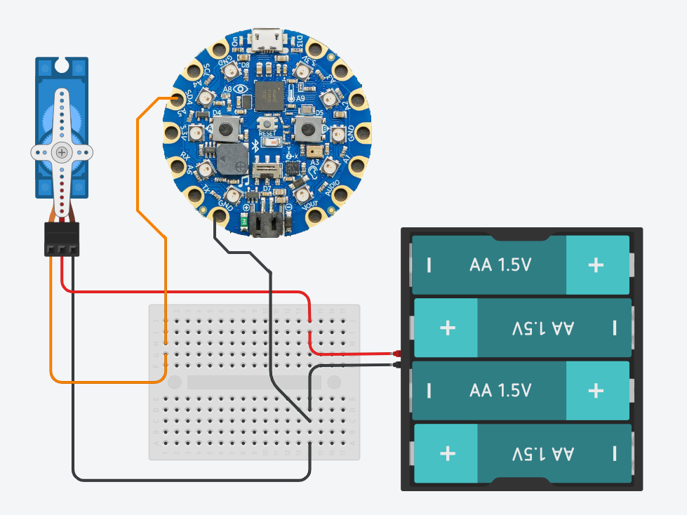
Schematic diagram showing the connections between a 4-AA battery pack, hobby servo, and CPB board. The small solderless breadboard is one possible approach for setting up the wiring; each row of five sockets connect together, so in this configuration it is joining the wires of like colors. On the CPB, any of the three GND pads may be used.
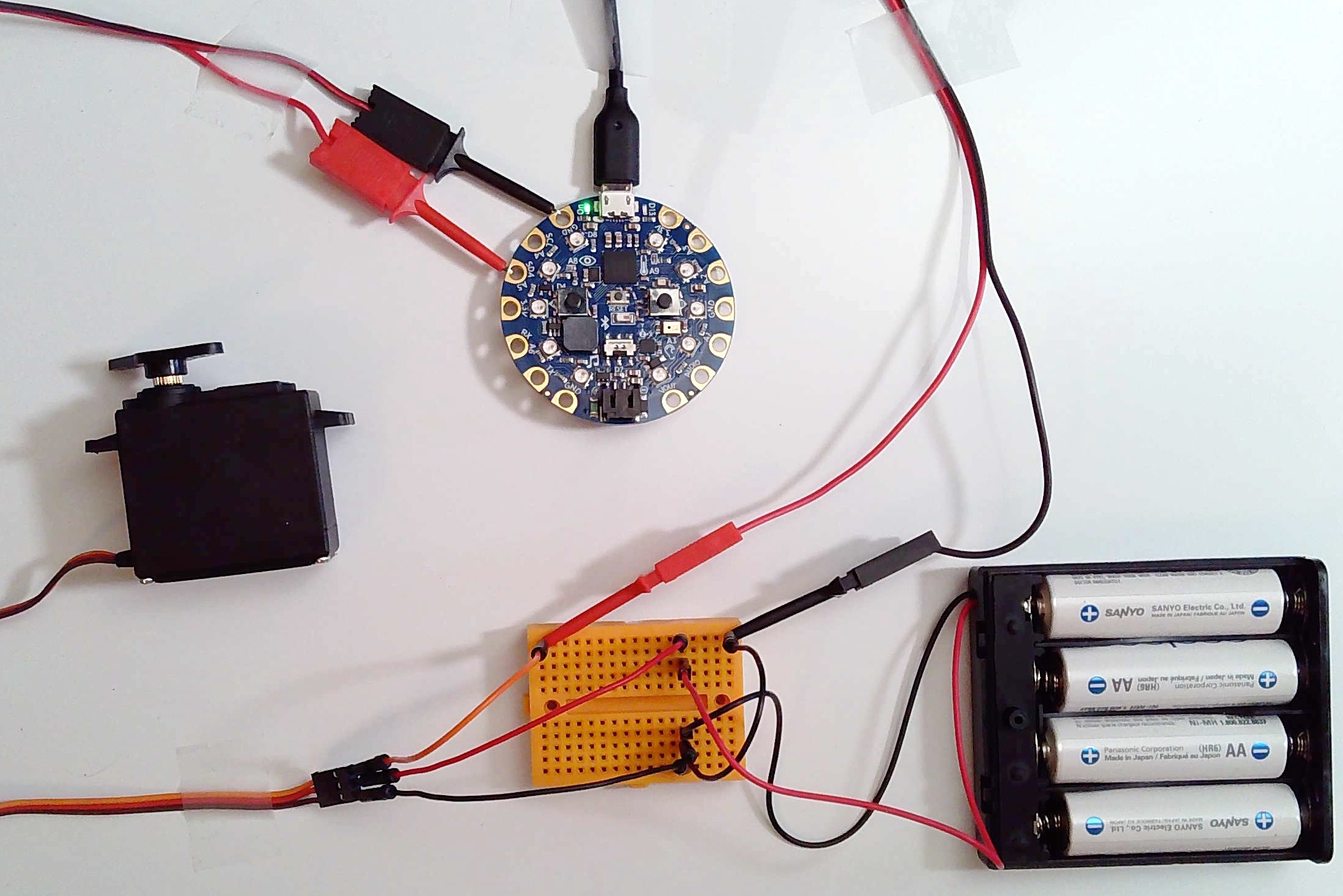
Photo of a physical realization the circuit. The clip jumper wires loop out of the photo from the CPB and down to the boardboard. The servo leads loop out of the photo and back to short male-male jumper wires which connect to the breadboard. The battery pack has breadboard-compatible leads; the red lead is positive and connects to the red wire (center) on the servo. The batteries are rechargeable NiMH AA, although alkaline also work.
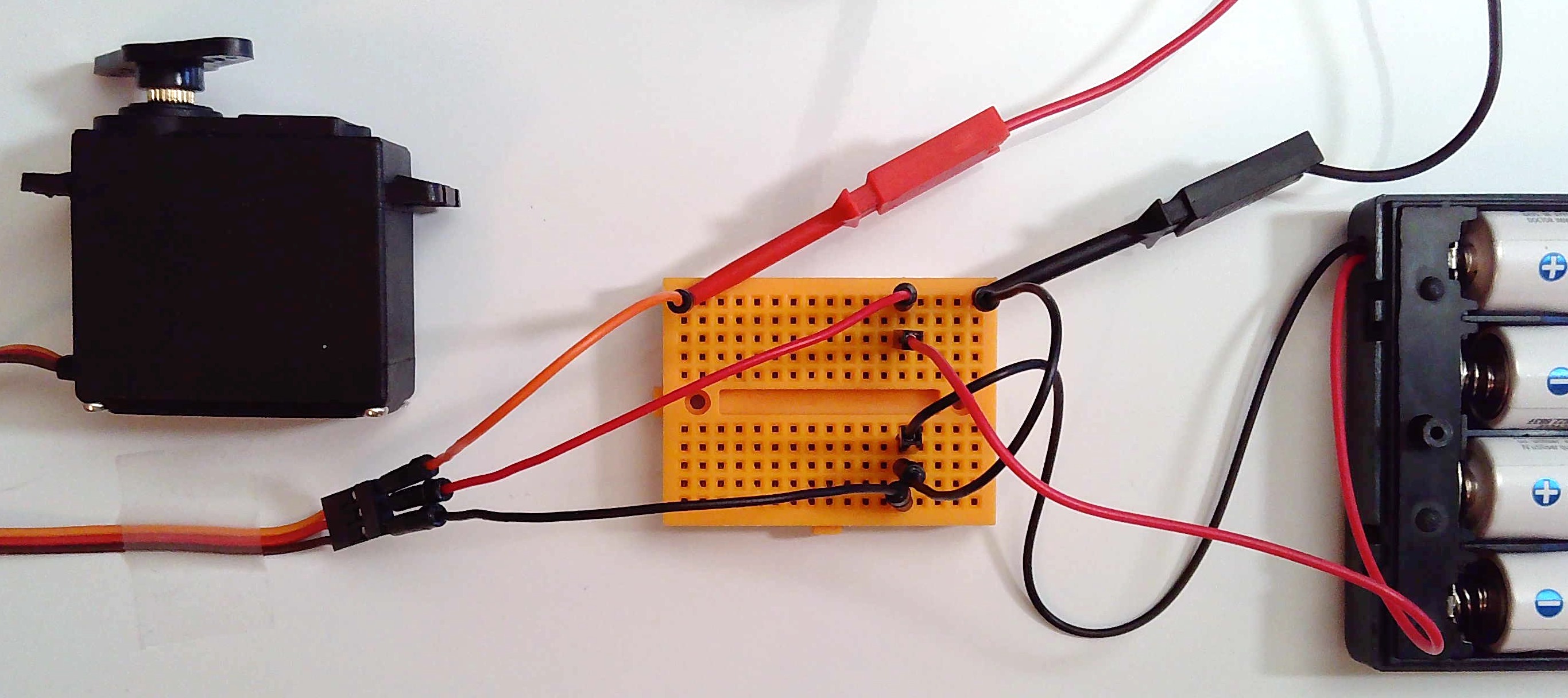
Detail photo centered on the breadboard.
Servo Sweep
This minimal sketch demonstrates the basic configuration for setting up a servo output and issuing motion commands. The resulting movement is shown in the following video.
Direct download: cpb_servo_sweep.py.
 1# cpb_servo_sweep.py
 2
 3# Demonstrate oscillating movement of a hobby servo.  Note that only a tiny
 4# micro-servo (e.g. "SG90 9g") is safe to drive directly off the board; in
 5# general, hobby servos require a separate battery supply.  The wiring for this
 6# is as follows:
 7#
 8#  1. The servo control line (typ. orange) connects to SDA A5
 9#  2. The servo ground line  (typ. brown)  connects to GND
10#  3. The servo power line   (typ. red)    connects to 6V battery
11
12# Related documentation:
13# https://circuitpython.readthedocs.io/en/latest/shared-bindings/pwmio/index.html#module-pwmio
14# https://circuitpython.readthedocs.io/projects/motor/en/latest/api.html#module-adafruit_motor.servo
15
16# ----------------------------------------------------------------
17# Import the standard Python time functions.
18import time
19
20# Import the low-level hardware libraries.
21import board
22import pwmio
23
24# Import the Adafruit helper library.
25from adafruit_motor import servo
26
27# ----------------------------------------------------------------
28# Initialize hardware.
29
30# Create a PWMOut object on pad SDA A5 to generate control signals.
31pwm = pwmio.PWMOut(board.A5, duty_cycle=0, frequency=50)
32
33# Create a Servo object which controls a hobby servo using the PWMOut.
34actuator = servo.Servo(pwm, min_pulse=1000, max_pulse=2000)
35
36# ----------------------------------------------------------------
37# Begin the main processing loop.
38while True:
39    print("Starting cycle.")
40    for angle in range(0, 180, 5):
41        actuator.angle = angle
42        time.sleep(0.02)
43
44    print("Reversing cycle.")
45    for angle in range(180, 0, -5):
46        actuator.angle = angle
47        time.sleep(0.02)
48
49    print("Pausing.")
50    time.sleep(0.5)
51
Sine Servo
This sketch moves the servo back and forth in a smooth motion. It is constructed as a non-blocking event loop, so this is a more practical starting point for combining with with additional sensor and actuator code. The resulting movement is shown in the following video.
Direct download: cpb_sine_servo.py.
 1# cpb_sine_servo.py
 2
 3# Demonstrate oscillating movement of a hobby servo using a non-blocking event
 4# loop structure.  This program style supports operating multiple devices for
 5# input and output.
 6
 7# Note that only a tiny micro-servo (e.g. "SG90 9g") is safe to drive directly
 8# off the board; in general, hobby servos require a separate battery supply.
 9# The wiring for this is as follows:
10#
11#  1. The servo control line (typ. orange) connects to SDA A5
12#  2. The servo ground line  (typ. brown)  connects to GND
13#  3. The servo power line   (typ. red)    connects to 6V battery
14
15# Related documentation:
16# https://circuitpython.readthedocs.io/en/latest/shared-bindings/pwmio/index.html#module-pwmio
17# https://circuitpython.readthedocs.io/projects/motor/en/latest/api.html#module-adafruit_motor.servo
18
19# ----------------------------------------------------------------
20# Import standard Python modules.
21import time, math
22
23# Import the low-level hardware libraries.
24import board
25import pwmio
26
27# Import the Adafruit helper library.
28from adafruit_motor import servo
29
30# ----------------------------------------------------------------
31# Initialize hardware.
32
33# Create a PWMOut object on pad SDA A5 to generate control signals.
34pwm = pwmio.PWMOut(board.A5, duty_cycle=0, frequency=50)
35
36# Create a Servo object which controls a hobby servo using the PWMOut.
37actuator = servo.Servo(pwm, min_pulse=1000, max_pulse=2000)
38
39# ----------------------------------------------------------------
40# Initialize global variables for the main loop.
41
42phase_angle = 0.0
43phase_rate  = 2*math.pi / 6.0  # one cycle per six seconds, in radians/second
44next_servo_update = time.monotonic_ns()
45next_status_update = time.monotonic_ns()
46
47# ----------------------------------------------------------------
48# Enter the main event loop.
49while True:
50    # Read the current integer clock.
51    now = time.monotonic_ns()
52
53    # If the time has arrived to update the servo command signal:
54    if now >= next_servo_update:
55        next_servo_update += 20000000  # 20 msec in nanoseconds (50 Hz update)
56        actuator.angle = 90 + 90 * math.sin(phase_angle)
57        phase_angle += phase_rate * 0.020
58
59    # If the time has arrived to display the status:
60    if now >= next_status_update:
61        next_status_update += 500000000  # 0.5 sec in nanoseconds (2 Hz update)
62        print(actuator.angle)
63