Soft Sensing Examples - Adafruit Circuit Playground Bluefruit
The following short Python programs demonstrate analog input features of the Adafruit Circuit Playground Bluefruit (CPB) board. These assume the board has additional external sensor circuits attached.
Each can be run by copying the program into code.py
on the CIRCUITPY drive offered by the board. The text can be pasted directly
from this page, or each file can be downloaded from the CircuitPython sample
code folder on this site.
Related Pages
Essential Documentation
Soft Pressure Sensor
The following sketch assumes that an external jumper and sensor are attached to the board. The A3 pad is programmed to be a digital input with a ‘pull-up resistor’. This internally connects the pin to the 3.3V supply voltage through a resistor and allows it to emit a small current. This current flows out S+ and back through S-, going through the resistive sensor. This current creates a voltage across the sensor which can then be sensed as a voltage on analog input A2.
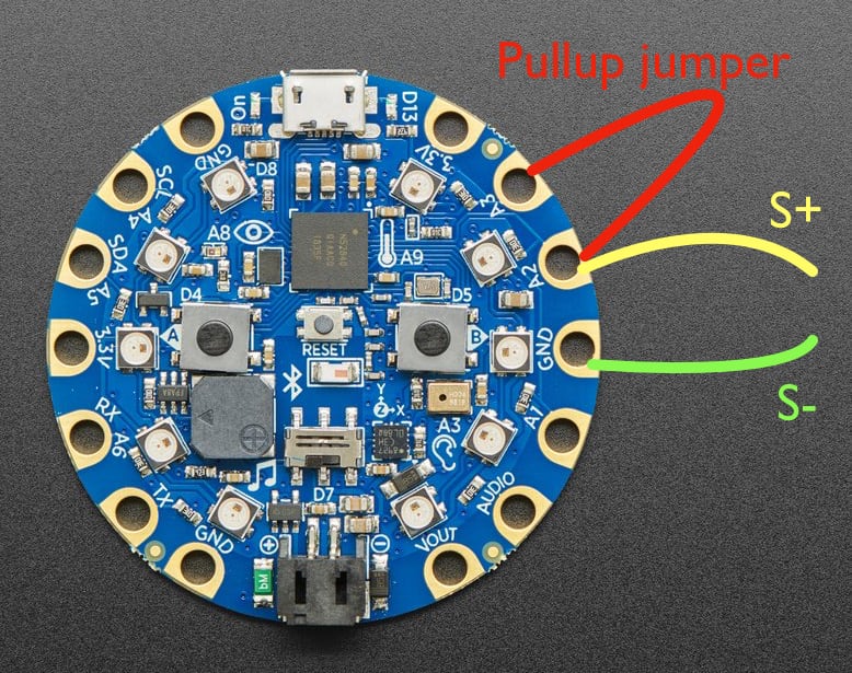
The resistive sensor is connected between A2 and GND, represented by the yellow S+ and green S- lines. The excitation current is supplied from A3 using a jumper wire.
Direct download: cpb_soft_analog.py.
The sketch prints values on the console in a list format which can be plotted in real time using the Plotter pane in the mu editor.
 1# cpb_soft_analog.py
 2
 3# Demonstrate measurement of an analog soft sensor input.  This is intended to attach
 4# to an external soft touch sensor hand-fabricated using conductive fabric and
 5# Velostat.  The electrical resistance of the sensor varies with pressure.
 6
 7# This example uses three pads on the board: A3, A2, and GND.  The A3 pad is
 8# used as a electrical current source by placing it in a digital-input mode with
 9# the internal pullup resistor enabled.  The pad then emits a small sensing
10# voltage which we use to probe the resistive sensor.  As mechanical pressure is
11# applied, the sensor resistance drops along with the voltage across the sensor.
12# This voltage is measured by the A2 pad, used in the analog-input mode.  Please
13# note that the sensor voltage follows an inverse logic: when not pressed, the
14# input value will be midrange, and when pressed, it will drop (possibly to
15# zero).
16
17# The wiring for this is as follows:
18#  1. One half of sensor connected to GND (either half).
19#  2. Other half of sensor connected to A2.
20#  3. Jumper wire connects A3 to A2.
21
22# Note on A3: the corresponding digital input is D10.  Empirically the internal
23# pullup resistor appears to be about 13.5K connected to 3.3V, e.g. it will
24# drive a 10K external resistance to 1.4 Volts.
25
26# ----------------------------------------------------------------
27# Import the standard Python time functions.
28import time
29
30# Import the low-level hardware libraries.
31import board
32import digitalio
33import analogio
34
35# ----------------------------------------------------------------
36# Initialize hardware.
37
38# Configure the digital input pin used for its pullup resistor bias voltage.
39bias = digitalio.DigitalInOut(board.D10)
40bias.switch_to_input(pull=digitalio.Pull.UP)
41
42# Configure the analog input pin used to measure the sensor voltage.
43sensor = analogio.AnalogIn(board.A2)
44scaling = sensor.reference_voltage / (2**16)
45
46# ----------------------------------------------------------------
47# Begin the main processing loop.
48while True:
49
50    # Read the integer sensor value and scale it to a value in Volts.
51    volts = sensor.value * scaling
52
53    # Every handmade sensor will have different properties, so the
54    # interpretation of the voltage value will usually need to be individually
55    # calibrated.  One way to accomplish this is by measuring the voltage
56    # response under different conditions, then applying additional scaling and
57    # offset to produce a normalized signal (possibly inverted).  For example,
58    # if the observed voltage ranges between 1.4 and 0.1 Volts, the input signal
59    # could be normalized to a [0,1] range as follows:
60    pressure = (1.4 - volts) / (1.4 - 0.1)
61
62    # Print the voltage reading and normalized value on the console.
63    print(f"({volts}, {pressure})")
64
65    # Limit the rate of the main loop.
66    time.sleep(0.1)
Soft Switch, Soft Pressure Sensor, Light, and Sound
This example extends the sketch to include a binary (on/off) soft switch input on A4 and adds an LED display of the results.
Direct download: cpb_soft_sensing.py.
  1# cpb_soft_sensing.py
  2
  3# Demonstrate measurement of several soft sensor inputs in both analog and digital modes.
  4# The values are indicated using the NeoPixel LEDs and speaker beeps.
  5
  6# This example uses the A3 pad as a pullup for a resistive sensor connected
  7# between A2 and GND.  The wiring for this is as follows:
  8#
  9#  1. One half of resistive pressure sensor connected to A2 (either half).
 10#  2. Other half of sensor connected to GND.
 11#  3. Jumper wire connects A3 to A2.
 12
 13# The A4 pad is used as a binary digital input with an internal pullup.  The
 14# wiring for this is follows:
 15#
 16#  1. One half of a soft switch sensor is connected to A4 (either half).
 17#  2. Other half of switch connected to GND.
 18
 19# ----------------------------------------------------------------
 20# Import any needed standard Python modules.
 21import time
 22
 23# Import the board-specific input/output library.
 24from adafruit_circuitplayground import cp
 25
 26# Import the low-level hardware libraries.
 27import board
 28import digitalio
 29import analogio
 30
 31# ----------------------------------------------------------------
 32# Initialize hardware.
 33
 34# Configure the digital input pin used for its pullup resistor bias voltage.
 35bias = digitalio.DigitalInOut(board.D10)        # pad A3
 36bias.switch_to_input(pull=digitalio.Pull.UP)
 37
 38# Configure the analog input pin used to measure the sensor voltage.
 39sensor = analogio.AnalogIn(board.A2)
 40scaling = sensor.reference_voltage / (2**16)
 41
 42# Configure the digital input pin used as a soft switch.
 43switch = digitalio.DigitalInOut(board.D3)       # pad SCL A4
 44switch.switch_to_input(pull=digitalio.Pull.UP)
 45
 46# Configure the NeoPixel LED array for bulk update using show().
 47cp.pixels.auto_write = False
 48
 49# Turn down the NeoPixel brightness, otherwise it is somewhat blinding.
 50cp.pixels.brightness = 0.5
 51
 52# ----------------------------------------------------------------
 53# Define functions used by the main loop.
 54
 55# Use the CPB NeoPixel LEDS as a dial gauge.  A normalized value between zero
 56# and one is shown as a spot of light like a dial needle.  The USB connector is
 57# considered to be the top; the LED to its right is zero, with values increasing
 58# clockwise around to the LED to the left of the USB.  The spot is anti-aliased
 59# to increase precision, i.e. it cross-fades between LEDs as the value changes.
 60
 61def update_LED_dial(value):
 62    # Clamp the input to the range limits.
 63    clamped = min(max(value, 0.0), 1.0)
 64
 65    # Convert the normalized value to an indicator angle in degrees with respect to the top.
 66    indicator = (clamped * 300) + 30
 67
 68    # Project the angle onto the NeoPixels. The list assumes the Neopixels are
 69    # uniformly spaced at 30 degree intervals, with the bottom position absent
 70    # (e.g. at the battery connector).
 71    for i, led_angle in enumerate((330, 300, 270, 240, 210, 150, 120, 90, 60, 30)):
 72        diff = abs(indicator - led_angle)
 73        if diff < 30:
 74            c = min(max(255 - int(10*diff), 0), 255)
 75            cp.pixels[i] = (c, c, c) # shade of gray
 76        else:
 77            cp.pixels[i] = (0,0,0)   # no light
 78
 79    # Send new data to the physical LED chain.
 80    cp.pixels.show()
 81
 82# ----------------------------------------------------------------
 83# Initialize global variables for the main loop.
 84
 85# Integer time stamp for the next console output.
 86next_print_time = time.monotonic_ns()
 87
 88# Previous touch value, used to detect changes.
 89last_touch = 0
 90
 91# ----------------------------------------------------------------
 92# Begin the main processing loop.
 93while True:
 94
 95    # Read the current integer clock.
 96    now = time.monotonic_ns()
 97
 98    # Read the integer sensor value and scale it to a value in Volts.
 99    volts = sensor.value * scaling
100
101    # Normalize the soft sensor reading.  Typically you'll need to adjust these values to your device.
102    pressure = (1.4 - volts) / (1.4 - 0.1)
103
104    # Update the LED dial gauge display.
105    update_LED_dial(pressure)
106
107    # Read and invert the soft switch input.
108    touched = 0 if switch.value else 1
109
110    # Emit a brief sound when the soft switch is pressed or released
111    if touched != last_touch:
112        last_touch = touched
113
114        if touched == 1:
115            cp.play_tone(392, 0.1)
116        else:
117            cp.play_tone(262, 0.1)
118
119    # Poll the time stamp to decide whether to emit console output.
120    if now >= next_print_time:
121
122        # Advance the time stamp to the next event time.
123        next_print_time += 100000000 # 0.1 seconds in nanosecond units
124
125        # Periodically print the readings on the console.
126        print(f"({volts}, {pressure}, {touched})")