dFAB Optitrack Setup and Calibration
(for Advanced Users and Admins)
Note: the following tutorial was recovered from the Spring 2014 wiki and could still use some updates.
In general, the cameras should only be moved with the permission of the dFAB monitors and other Admin users, since it requires careful attention to calibration procedure for subsequent use to be accurate. Nevertheless, projects will frequently require adjusting the field of view of the motion capture system for specific tasks, so these instructions will be needed fairly frequently.
For ease of use, the current calibration set should be named under a standard name within the Motive application on the lab PC.
Calibration Overview
The overall Optitrack calibration process has the following major steps:
- locating the cameras
- capturing wand motion to compute camera-to-camera calibration
- setting the ground plane to define the motion capture coordinate system
For use with the robot, the additional required steps are as follows:
- installing the robot reference marker set
- positioning the robot to the reference pose,
- defining the Ground and Robot reference bodies
- capturing the robot position within motion capture space
- computing the transform from mocap to robot coordinates
Aiming Cameras:
- open Motive Software (on Desktop)

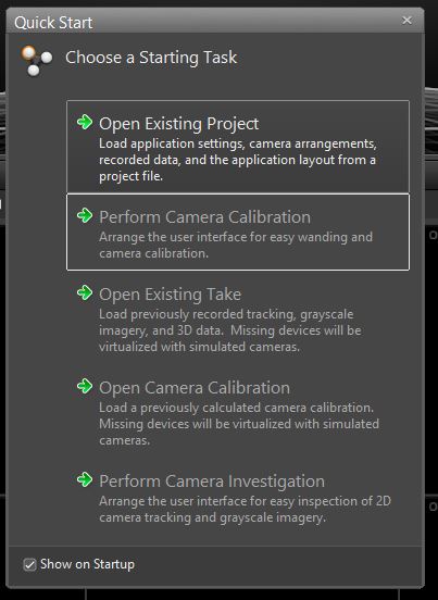
- Select Perform Camera Investigation from quick start menu
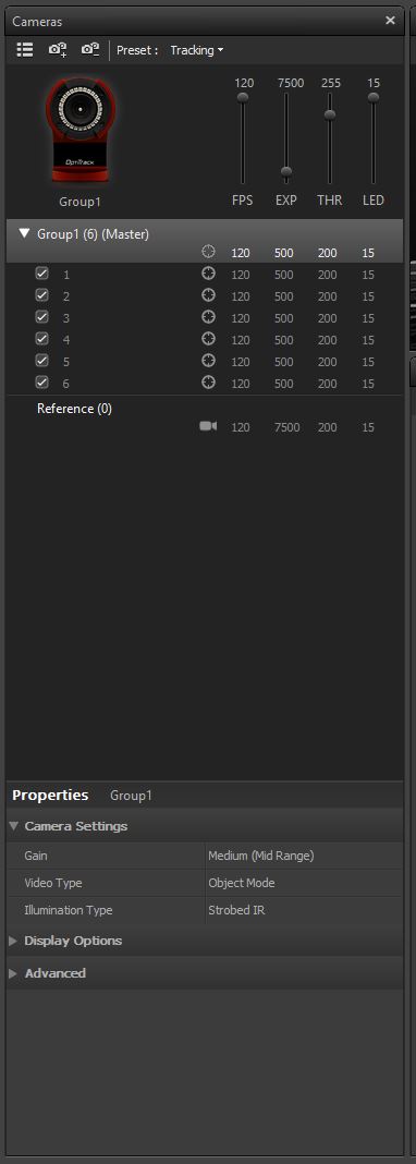
- in Cameras tab on right side of window, select the preset drop-down menu (default is tracking) and change to Aiming.
- The aiming mode makes it easy to see what the camera sees, which greatly aides in positioning the cameras
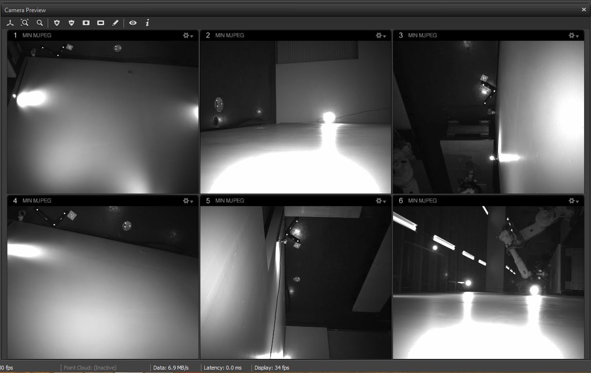
The number displayed on each camera’s LED corresponds to its number in the Camera Preview Window
(image showing the camera)
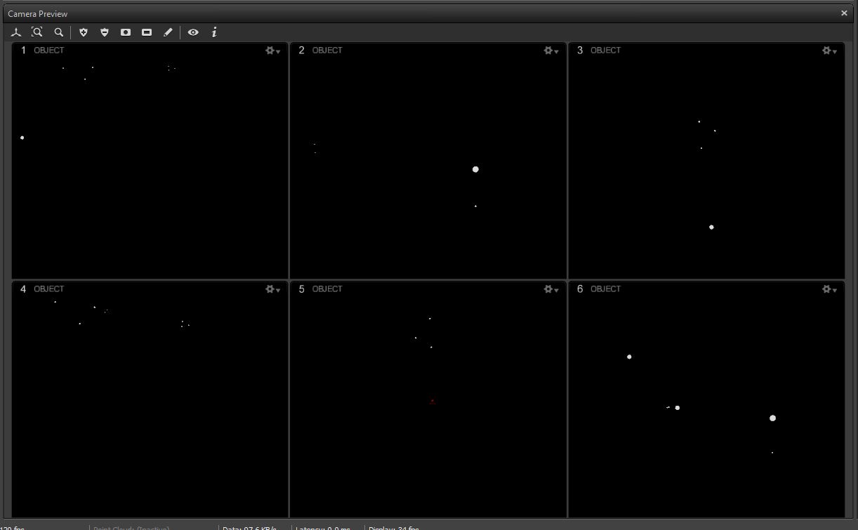
when cameras are properly positioned, make sure to change the preset back to tracking.
- otherwise the cameras won’t track.
- quick way to tell is that there are x’s next to each camera (image showing x)
for more customization, you can select individual cameras and change the FPS, exposure, threshold, and LED values. In most cases this is not necessary. The presets do everything you will need for calibration.
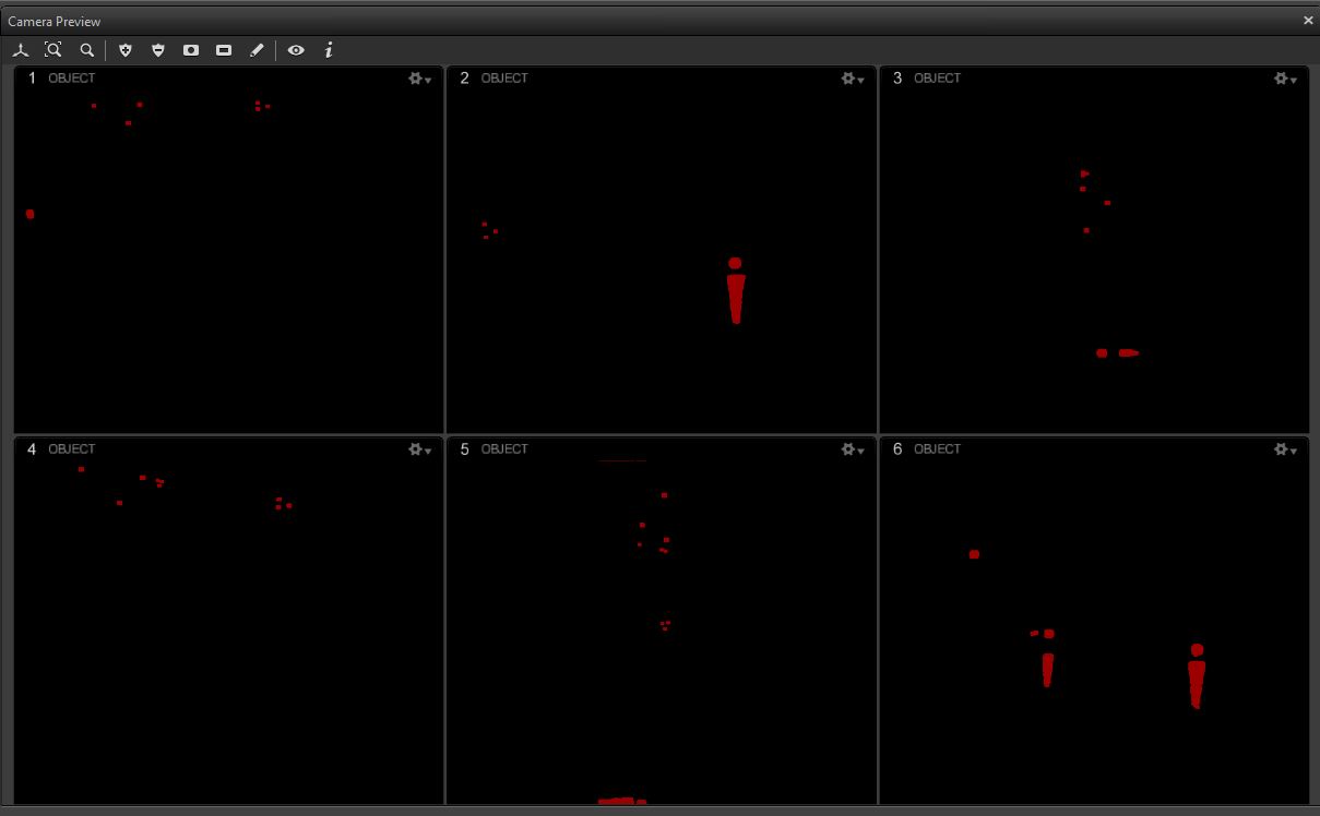
Checking the Camera Views
- Select Perform Camera Calibration from quick start menu
- Make sure that no markers are within the capture space
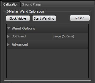
in the calibration window select Block Visible to apply a filter to the cameras that will eliminate any reflective surfaces showing up
- it is good practice to do this whether or not any reflective surfaces are showing up
- this ensures that the camera won’t pick up any stray reflections
- once completed, blocked reflections will appear Red
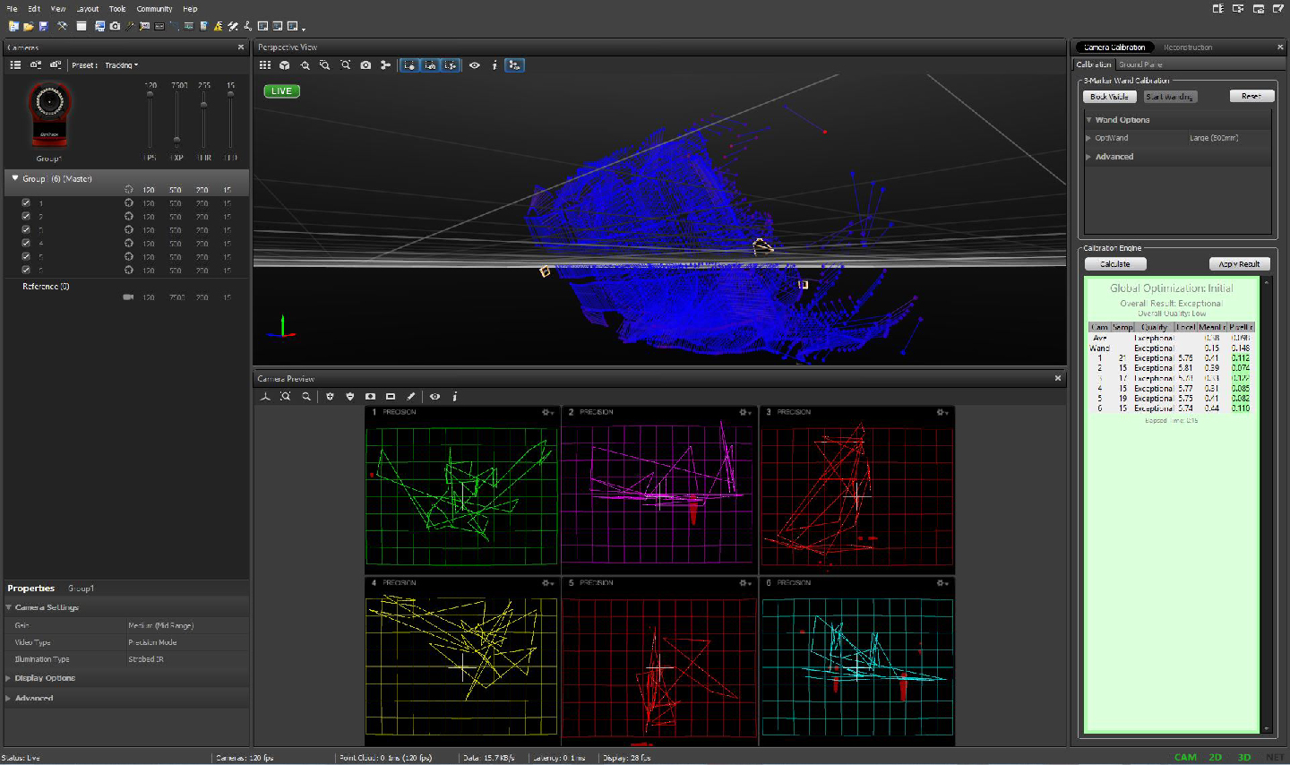
Capturing Wand Motion
- press Start Wanding button
take calibration wand, and wave it around in capture space until all 6 camera windows are covered.
try to wand in different directions and orientations
(image of person wanding)
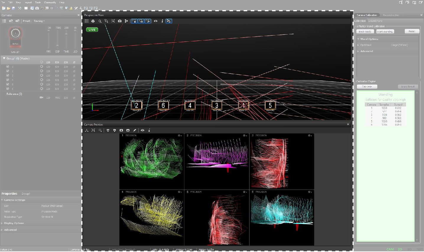
- When wanding is complete, you should see something like this:
- It is important to try to cover as much of each camera as possible. This will help increase the accuracy of the calibration file
- press Calulate button to begin the calibration engine
- let it run until it gets to the desired results.
- for best accuracy let it run until it reaches Very High and Exceptional levels
- press Apply Result button, to apply the Calibration
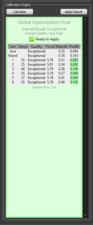
- while the software is running the calibration optimization, you will see something like this:
save the calibration file to ???folder as base_calibration_date
need to set up a folder to save Calibration files to)
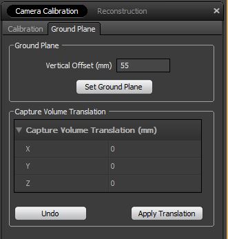
Setting Ground Plane (mocap origin and orientation)
Our current convention is to place the ground tool (a 300-400-500 mm triangle with 3 markers) level on the floor, with the short axis flush against the wall, and the long axis with the Z arrow pointing away from the wall.
- place the ground plane calibration tool in the scene, ensuring that it is viewable by at least 3 cameras
(image of Ground Plane tool in space) (image of Ground Plane tool in software)
- press Ground Plane button
Saving Conventions & Locations
All Motion Capture files will be kept in the dFAB Base Files folder which can be found in Documents
(image of folder)
C:UsersdfabadminDocumentsdFAB Base FilesMotion Capture
Inside the Motion Capture Folder there are 3 folders, 3 base files, and a README.
- _Admin
- _User Files
- Rigid Body Library
- dFAB_Base Calibration_(some date).cal
- dFAB_Base Project_(some date).ttp
- dFAB_Base Wanding Timeline_(some date).tim
- README
(image of files)
_Admin
Any time new version of one of the dFAB_Base files is created, a copy of the old file should be placed in the _Admin folder. A backup copy of the current version of the file should be placed here as well in case a General user overwrites a base file.
- It is important to follow the naming structure when creating/saving newer dFAB_Base files
_User Files
All General Lab Users should keep and save any files in the _User Files folder. It is advisable to create a personal folder here to keep everything organized
Rigid Body Definition Library
- Set up a series of rigid body tools that are predefined and can be loaded by general user.
- can be included in Base Project File
dFAB_Base Project
Shows how to setup and save a Project file that can be dFAB_Base Motion Capture
- includes calibration data, rigid bodies, sample takes
- preferred file for general users to open
- should keep a backup of file somewhere else in case it gets changed
dFAB_Base Calibration
Keep an updated calibration file that can be loaded
dFAB_Base Wanding Timeline
The wanding timeline can be used in creating a calibration file
- Only use if you are sure that cameras have not been moved since this file was created
Calibration for Robot Use
The motion capture system reports trajectories within its own coordinate system defined when the “ground plane” was set. To use the data with the robot, a separate calibration must be determined which relates this coordinate system to the robot coordinates. This is performed by using the system to measure the position of a known robot reference marker positioned at a known point in robot space. This allows solving for the transform which relates the two coordinate systems.
Robot reference marker set
The robot marker set is an acrylic triangle with four large markers attached: three in a 300-400-500 triangle with the fourth at the centroid. It must be bolted to a standard tool plate such that the long axis of the triangle points along the TCP +X axis.
The reference location may change based on the overall envelope of the motion capture region. The ABB should have a module named MocapReference.mod with a single motion instruction to drive the robot to the known reference location. The position should be recorded for later checking against the TCP values in the calibration.params file used for computing the calibration.
- run the MocapReference.mod program
- record the position and orientation of the TCP from the teach pendant
Defining Ground and Robot Bodies
The calibration script expects to find the robot body defined as Robot. It is also a good idea to define the ground marker set as Ground for later validation of the data.
Capturing the Robot Reference
Perform a normal capture recording of the Ground and Robot bodies. Since the scene is entirely static, a few seconds of data is sufficient. Trajectorize and save to CSV file as described previously.
Computing Transforms
There are two command-line scripts within the [[resources:github|dFab Python library]] for post-processing CSV files. Each can accept a ‘’–help’’ option to display the program inputs and options.
If the robot calibration file was recorded as “Cal-March-20-2014.csv”, then the following command will compute the mocap->world transform, reading the mocap coordinate convention from calibration.params, and writing a new calibration set back to the same file (while saving a backup).
<code>estimate_mocap_calibration “Cal-March-20-2014.csv” –param calibration.param</code>
The resulting file is plain ASCII (JSON format) and can be decoded by inspection.
Extracting Mocap Trajectories
The trajectory for a single rigid body can be extracted and converted to robot coordinates with another script. The resulting file is a simple ASCII file describing the coordinate frame trajectory, in a form which can be easily read into Rhino and Grasshopper.
Given a file “Traj-001.csv” with a body named “Tool”, and a current calibration.params file, the following command will create a new ASCII trajectory file:
<code>trajectory_from_mocap calibration.params Traj-001.csv -b Tool -o Traj-001.traj</code>
There are additional options to change the subsampling rate and show more detail, try the ‘’–help’’ option for details.