dFAB Optitrack Motion Capture System
The OptiTrack motion capture system in the MM C4 dFAB Robot Lab can be used for measuring the movement of multiple rigid objects. It is typically used to record data files for analysis but also supports real-time streaming output.
The system is located in the robot workspace, so use will generally require reserving time using dFAB Reservations.
Contents
Basic Mocap Setup and Operation
This is a brief tutorial intended for students using the system and covers setting up objects to track, capturing motions, and exporting motion capture data. Advanced users and admins may wish to consult dFAB Optitrack Setup and Calibration.
Additionally, more help can be found at:
A cached copy of the OptiTrack Quick Start Guide is available to logged-in users.
Starting the Optitrack Motive Software
- Open Motive software (shortcut on desktop):

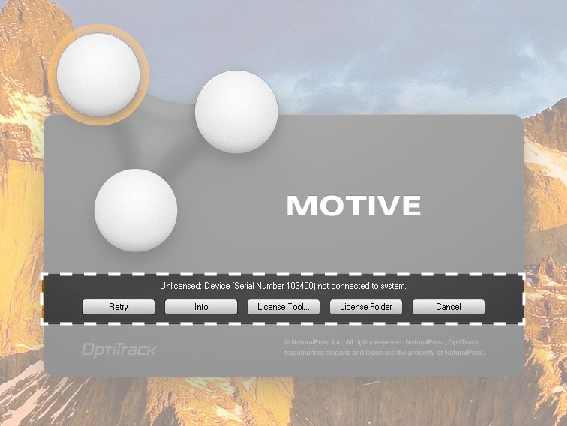
- If the following window appears, the license hardware key is missing:
- When first opened, the Quick Start menu will appear with 5 options:
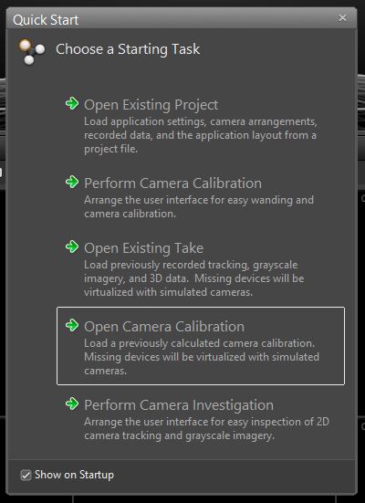
Select Open Camera Calibration. Your instructors can provide the path to a Motive project file (extension .ttp) with the current default camera calibration.
If you are a general user, make sure to always use SAVE AS when saving project files in order to avoid overwriting the provided file.
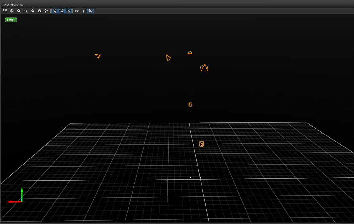
Check that the layout and orientation of cameras matches the lab setup. If everything is properly calibrated, the cameras should appear in the proper position and orientation.
Defining Rigid Bodies
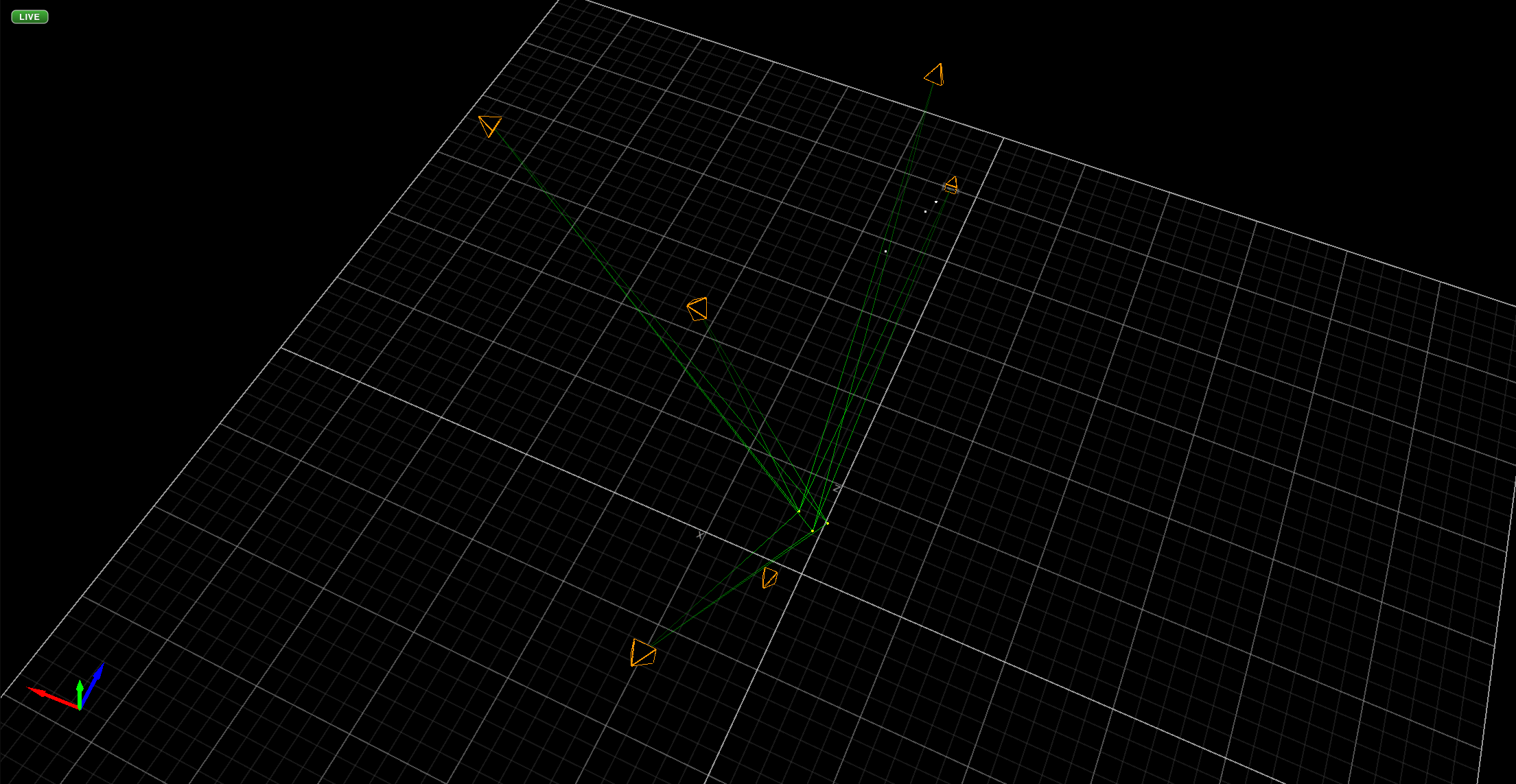
The motion capture system sees each marker as a bright point reflecting light back into each camera. With proper calibration, it can correlate which bright points in each view represent the same marker in space, and then compute the 3D position of each marker within the coordinate system defined during calibration.
The next stage of setup is to define which clusters of markers are actually attached together to each rigid body. This allows computing the trajectory for each rigid body with full position and orientation, and also provides additional constraints for associating markers with image points.
To define a new body, first place the object with markers attached within the scene in a well-defined reference orientation. E.g., if the object has a linear edge, place that edge against the wall to be aligned with the robot +X axis, and if it has a flat face, rest that flat face on the floor or table.
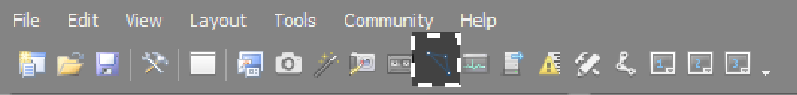
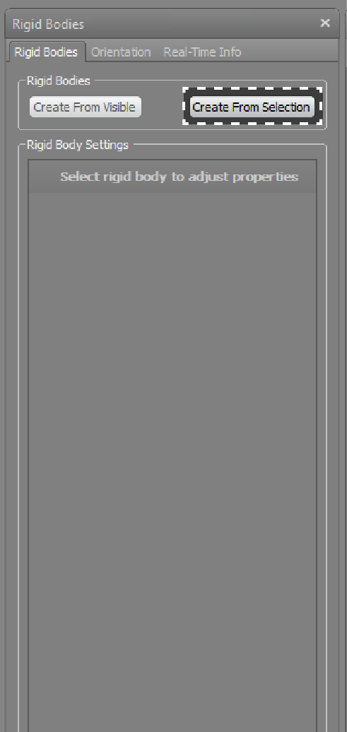
- Press the Rigid Body button to bring up the Rigid Bodies Window:
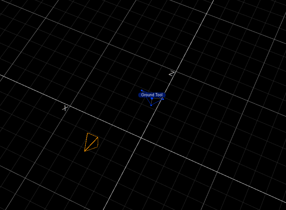
- Shift-click on each attached marker within the 3D view:
- Select “Create From Selection”:
- Select the recently created Rigid Body in the Modeling Window:
- Rename the rigid body in the Rigid Bodies Browser:
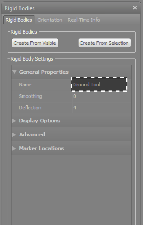
Please choose names consistently and carefully, as they will appear in data files and be needed in post-processing. We have a few conventions so far: the ground reference triangle is defined as “Ground”, the robot calibration reference triangle is defined as “Robot”, the plastering trowel is defined as “6 Point Trowel”.
The Motive software assigns the origin of the body-local frame at the centroid of the markers. It assigns the orientation of the body-local frame to be aligned with the motion-capture coordinates at the moment of definition. This is the reason for physically aligning the body features with the coordinate axes, as it eases the interpretation of the orientation component of the trajectory.
Capturing and Recording Motion
- Select Capture Layout Button from top right hand corner
- Press the Record button and begin the motion capture take. If you are simultaneously recording video, it is recommended to ‘slate’ the motion by beginning with a clearly defined gesture which can be precisely observed in both the video and mocap data.
- You may wish to set a custom name for each take, and optionally a timer for a delayed start:
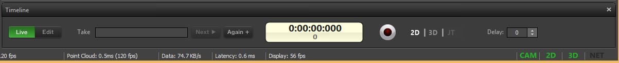
- For playback of the selected take, press Edit to switch to playback mode:
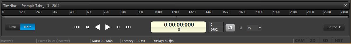
Trajectorize: 2D to 3D Conversion
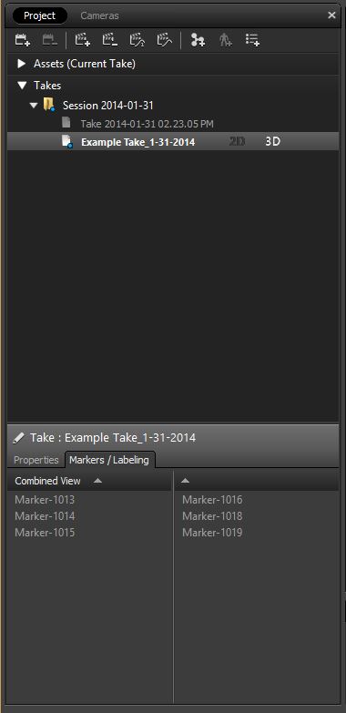
- Once finished recording, the take will appear in the project window on the left side of the layout.
- Initially the system records 2D point data. In order to get the 3D data we need to trajectorize the 2D points:
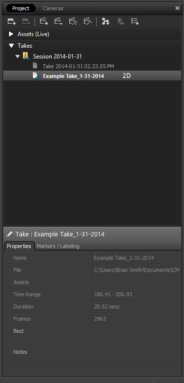
- Right click on the take that you want to export, and select trajectorize:
Export: Saving Trajectories to CSV Files
- Once the data has been trajectorized, it is ready for export. Right click on the take you want to export, and select export tracking data. Select CSV format and save to your own folder:
Project Files: Saving the Scene Configuration
- The calibration and takes can be saved as a packaged Project file, that can later be opened and resumed. This saves all takes, trajectories, rigid bodies, etc.
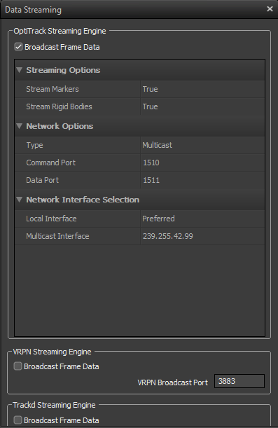
Streaming Settings
If you will be using the live motion capture data, e.g. streamed into a Grasshopper sketch, the streaming engine shoudl be configured as shown.
Motive Software Version
For reference, the dFAB lab has Motive version 1.5 with a license for rigid body tracking. This version writes Optitrack CSV Version 1.1 format files, and uses NatNet 2.5.0.0 streaming format.