by Hang Wang & Varun Gadh
Abstract
Touch & Melt explores human-machine collaborative fabrication in a process that leverages an innate human skill and a functional robotic skill. The ability to find and focus on engaging physical facets of objects and unique textures on object surfaces – and relatedly, the ability to easily generate an intricate pseudo-arbitrary path of travel on and about an object – is a distinctly human one. The ability to move in the precise and consistent manner needed for many forms of fabrication is an ability firmly belonging to machines.
Using MoCap (Motion Capture) technology to collect tactile scanning data (following the human end-effector path), this fabrication methodology generated an abstracted version of the form of the scanned object. The abstraction seeks out highlighted features of particular tactile importance by finding regions in which the highest amount time has been spent.
Next, the process uses a histogram of touch density to generate contours for a robotic arm to follow. Finally, the robotic arm manipulates a piece of polystyrene plastic under a hot air rework station; its motion follows the generated contours. The resulting melted plastic is an abstracted representation of the human interpretation of the target object.
Objectives
The project objectives were as follows:
- To observe the tendencies of human tactile scanning; what kinds of edges, forms, textures, and other facets are of the most tactile importance
- To test the hypothesis that, when scanning the same object, different users would generate different outcomes when using the system
- To find the appropriate material, stock thickness, heat-applying robot tool, contour order, temperature, air pressure,
Process
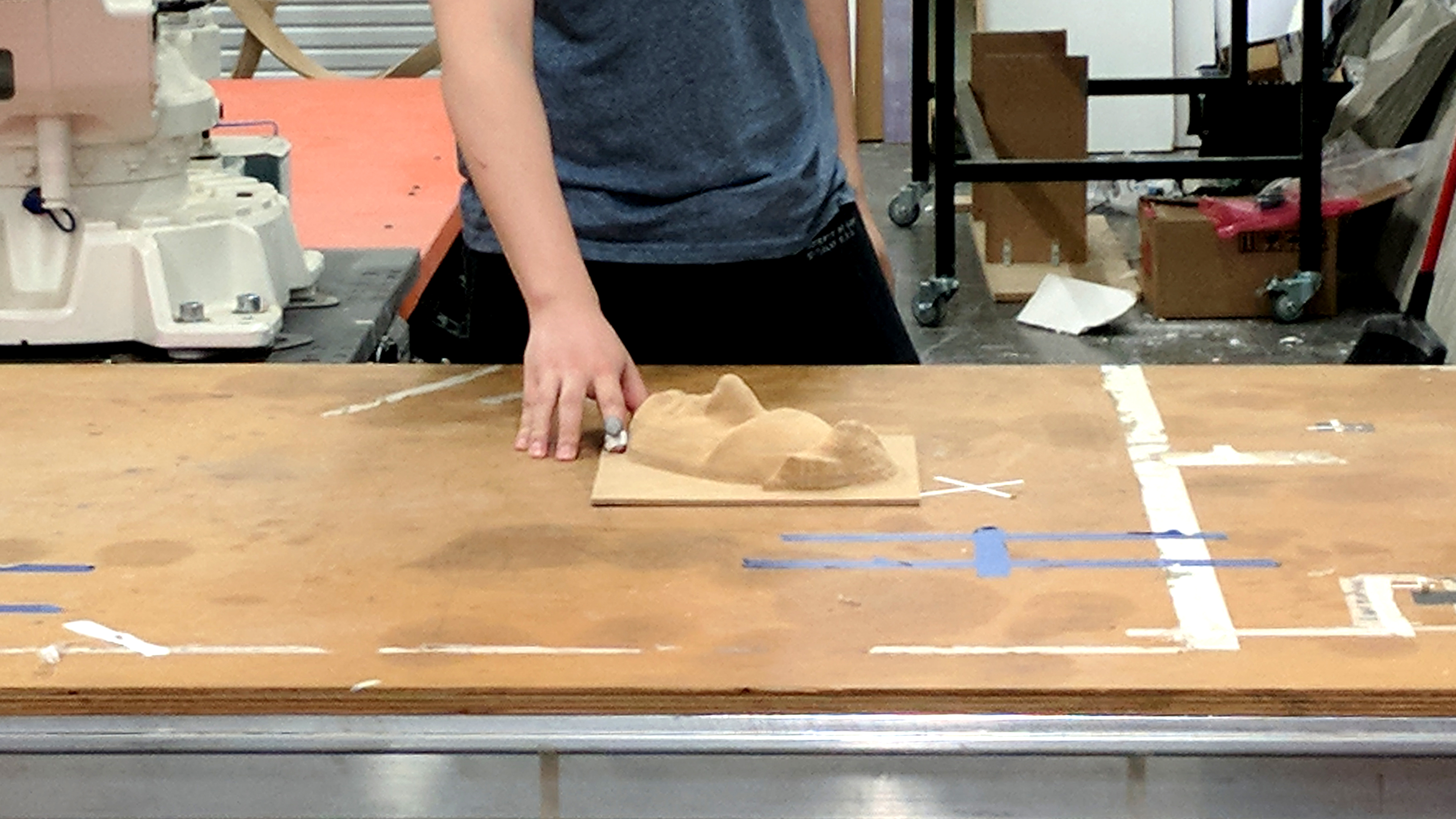
For the purposes of explanation, this description will follow the scanning of a single object (pictured below) by two different users.

Using either a marker or a set of markers (depending on the software and physical constraints) mounted to a glove or finger, a user scans a target object (in this case the face of one of the project creators).
The MoCap system records the scan and collects three-axis position data.
The position data is then exported and parsed through a Python script into a set of points in 3D space to be represented by Grasshopper in Rhino.
The 3D point set is flattened onto a single plane and overlaid upon a grid of squares. The point densities over each square are mapped to the corresponding squares and a heat map representing touch density is generated:
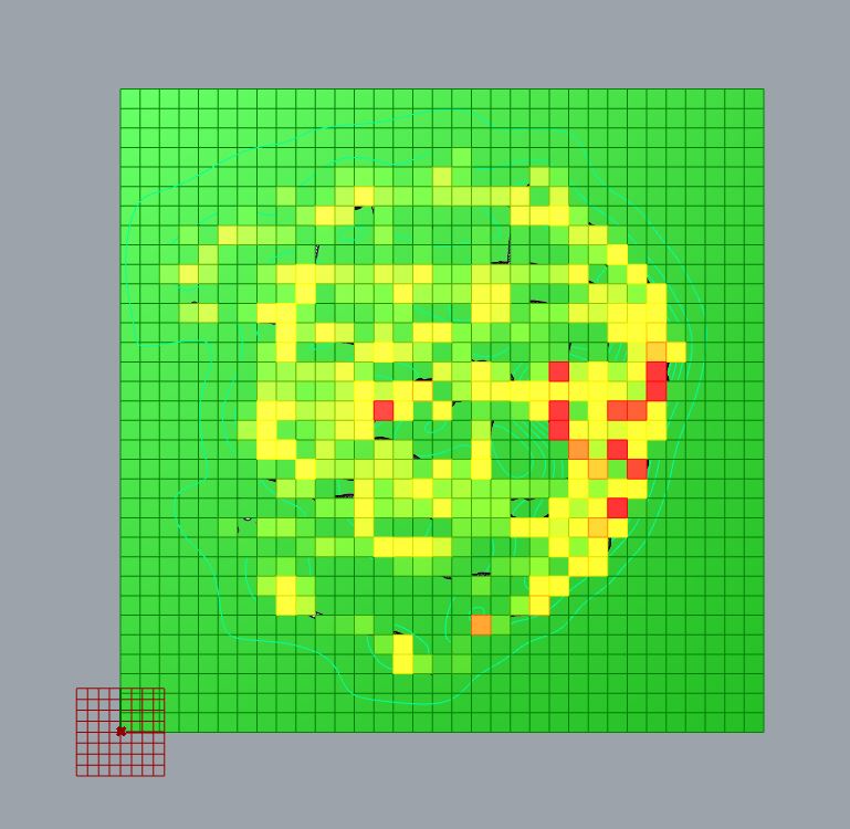
In this heat map, the gradient green-yellow-red represents an ascending touch density value range.
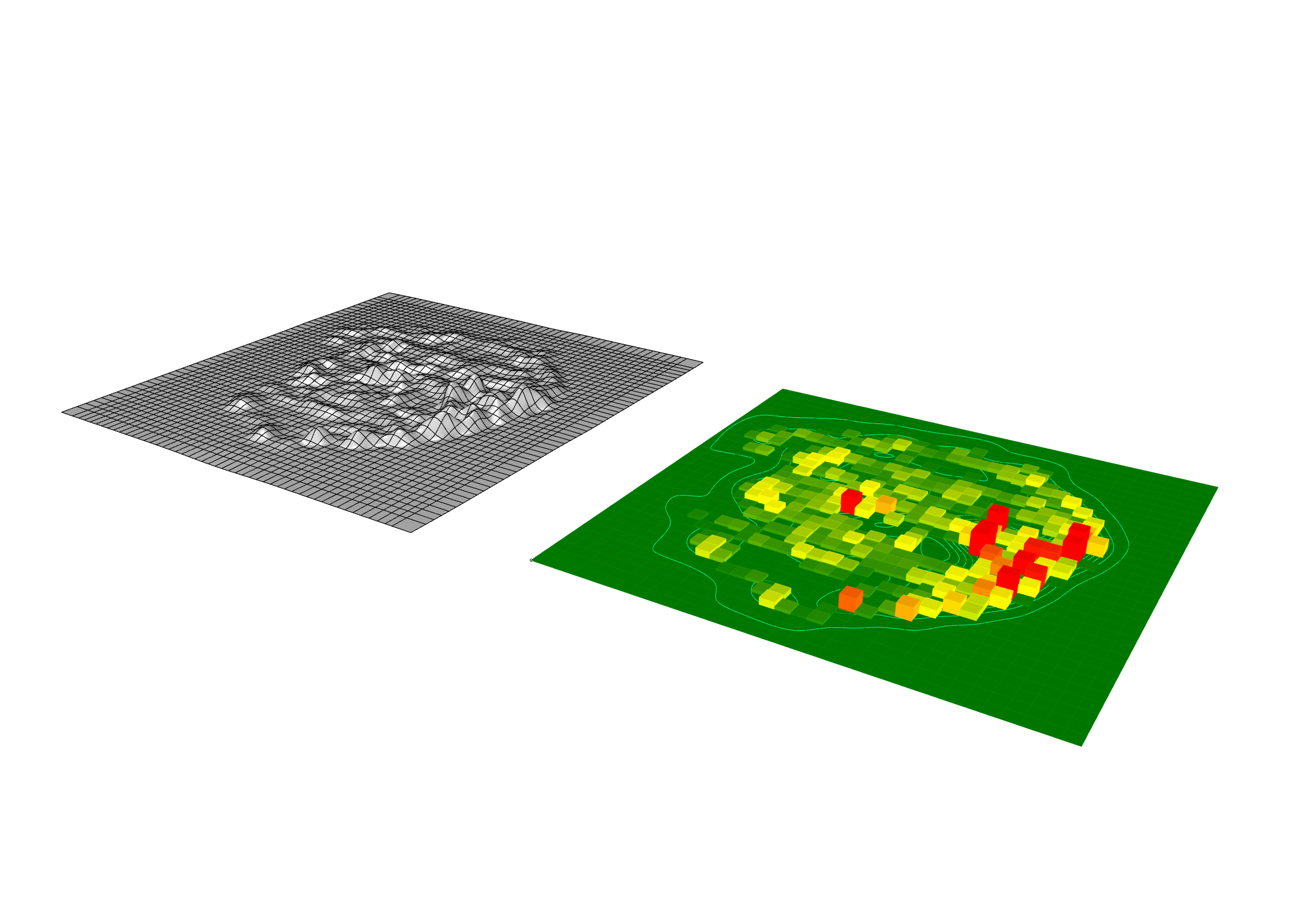
Once the touch density values have been mapped onto a grid, each grid square is raised to a height correlated to the touch density value it represents and a surface is patched over the raised squares.
From this new smooth surface, a set of contours (below) is extracted by slicing the surface at an interval set by the user. (For a deeper understanding of how the contour generation works, read up on the Contour function in Rhino; the two actions rely on the same principle).
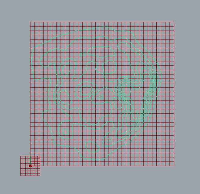
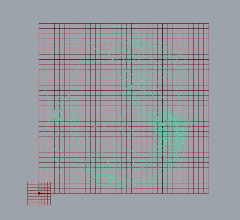
These contours are broken up into sets of paths for the robot arm to follow:
The process retains a fair amount of legibility from collected data to robot path.
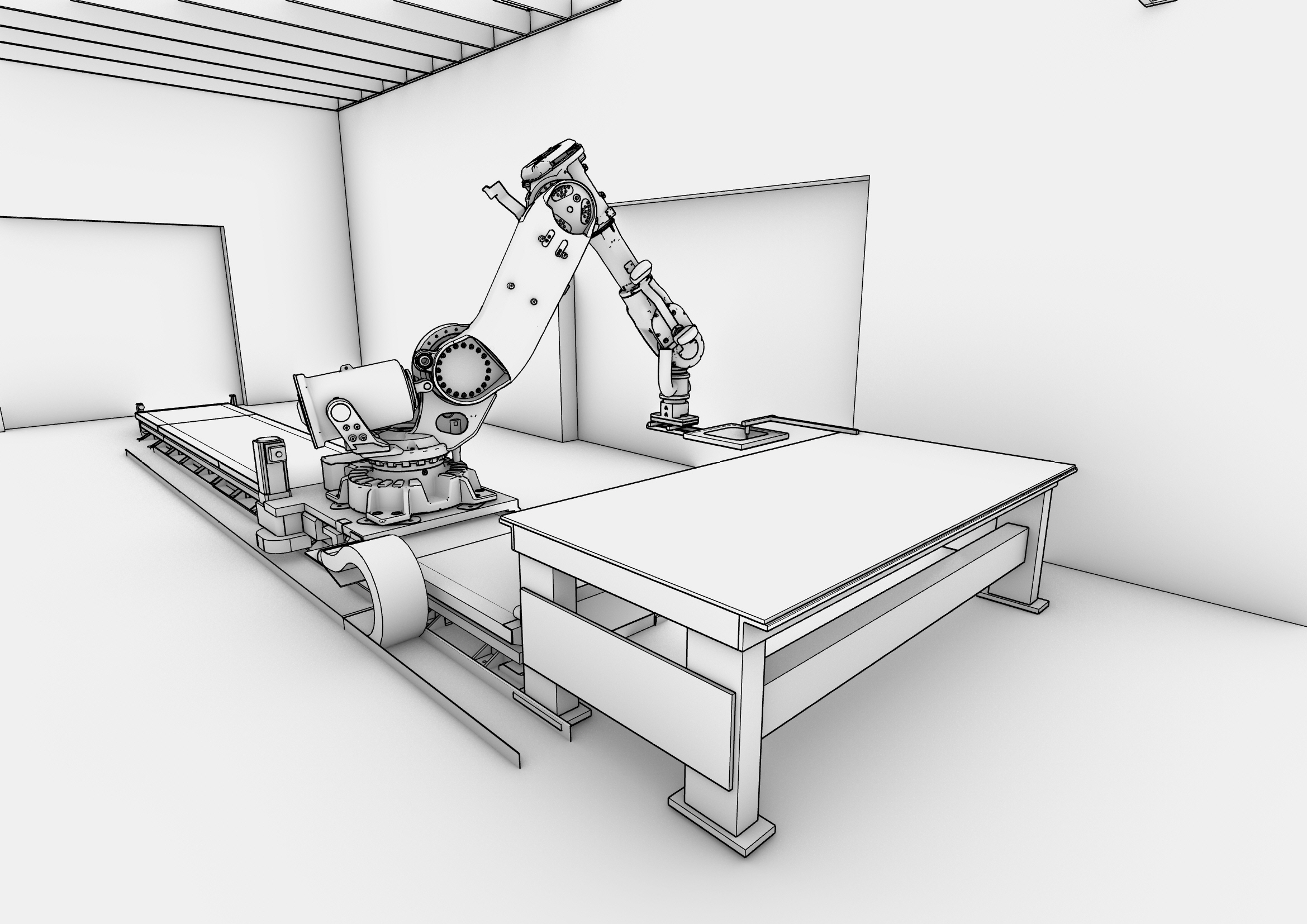
The robot arm guides the polystyrene stock under the heat gun along the contour paths.
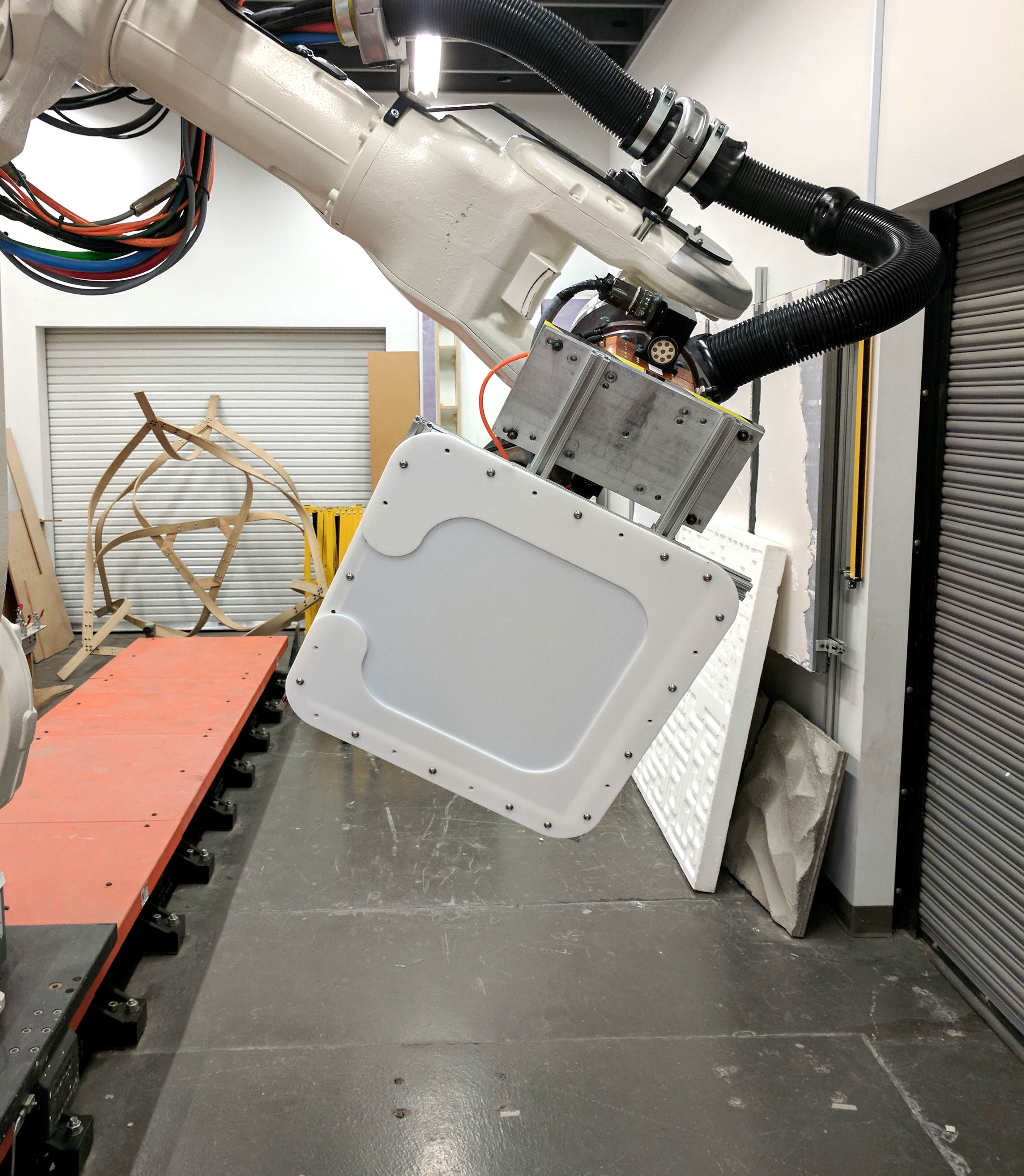
The polystyrene is mounted to a clamp on the robot. The robot arm guides the polystyrene stock under the heat gun along the contour paths.
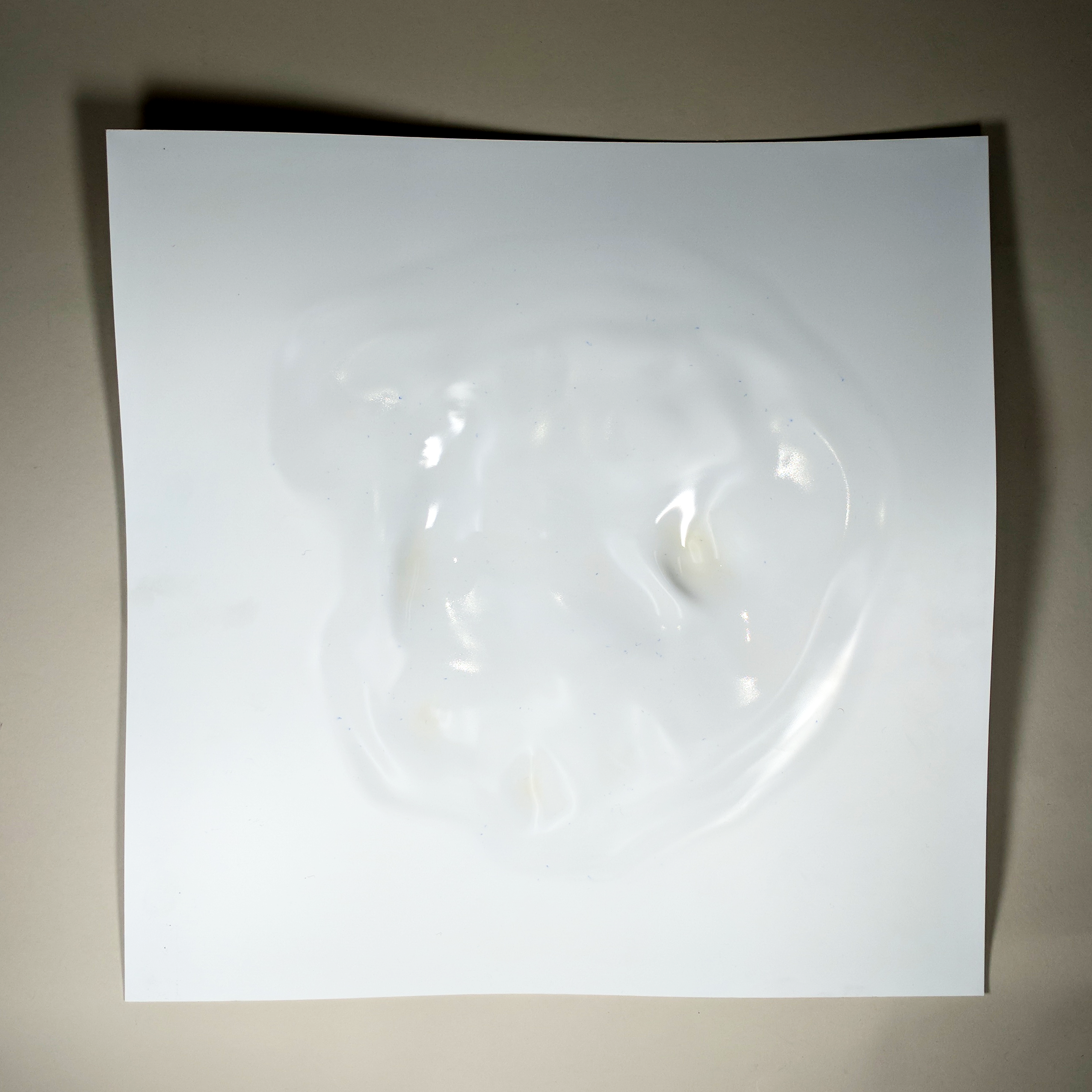
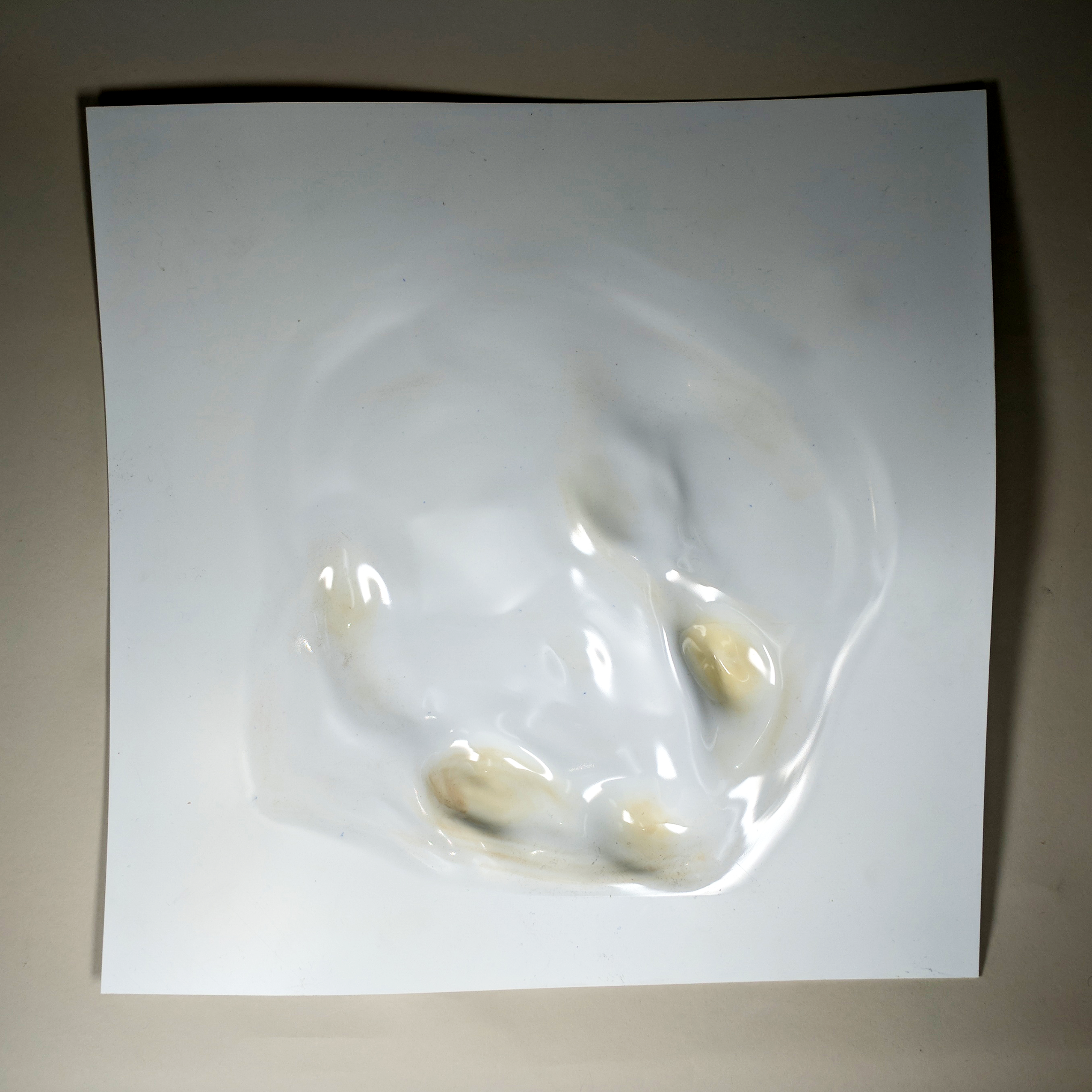
After several tests (and a bit of singed plastic) we were able to find the fabrication process that is the effective balance of expressiveness and information retention!
The problem of reaching that effective fabrication process, however, was non-trivial. One of the factors in the manufacturing process that required testing and exploration was contour following order.
As we wanted to maximize the z-axis deflection of the material due to heat (in order to have the most dramatic and expressive output possible), we initially believed that we should address concentric contours in an in-to-out order. This would minimize the distance between the heat gun and each subsequent contour. However, we learned that – as our contours are relatively close together – the inner rings would experience far too much heat and hole would form in the material, distorting the rest of the material in a way that we viewed as non-ideal for preserving the contour information. As such, we thought it wise to travel out-to-in to decrease the amount of heat experienced by the inner contours.
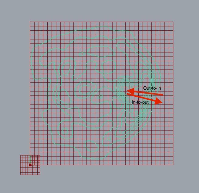
When we tested out-to-in order, however, the points in the material at which the inner contours would be had traveled too far vertically away from the heat gun to be effectively melted. Finally, we settled on addressing each layer of contours in the order they were sliced. For example, the outermost contour in the diagram below (1) would be followed first. Next, the second smaller concentric contour along with the small contour that is of equivalent concentricity (2) would be followed. The subsequent round of contours would include those contours marked (3). This continues until the final layer of concentricity is reached. This heating order proved to be the most effective because it was an effective balance of summed heat over regions that were meant to be deformed, but not enough concentrated heat in a small place to cause large holes to appear.
Outcomes
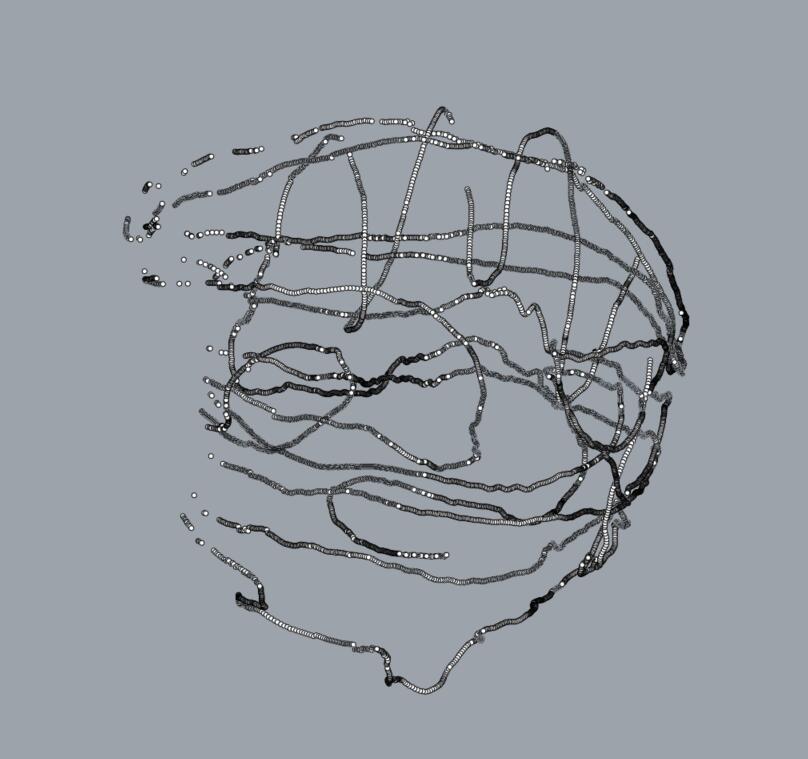
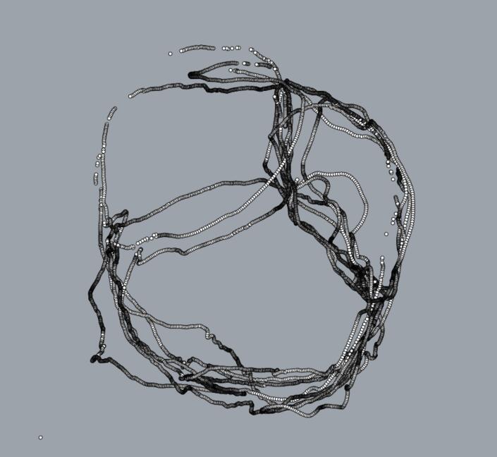
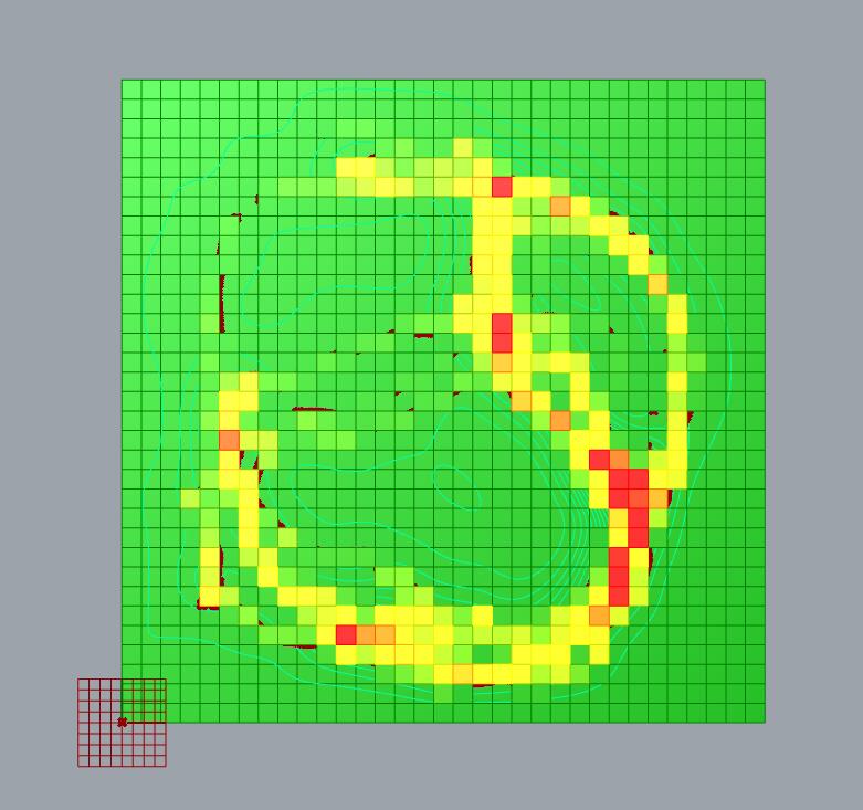
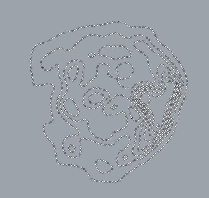
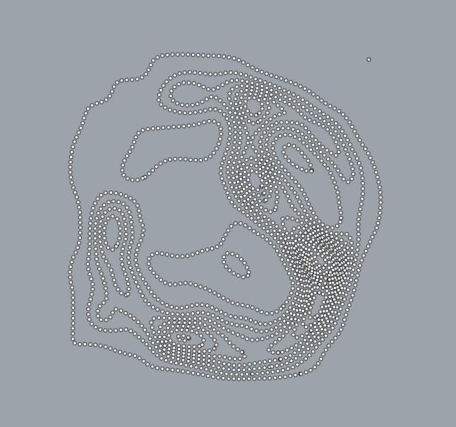
When different users scan the same object, results can very dramatically in both path and touch density. For example, two volunteers who were relatively unfamiliar with technical aspects of the system scanned the same object (the face of one of the project members) and approached the scanning in completely different ways; the speeds, features of primary focus, and scanning goals of the participants varied dramatically. Seen below, the paths are structurally different and repetitive within their own patterns.
In terms of investigating what physical facets are the most engaging, we were able to glean information primarily about faces as that was our chosen object set of interest. Generally speaking, the nose tip, nose edges, jawline, and lower forehead seem to be the areas of primary interest. This seems to be due to the clearly defined curvature of those features. Areas of relatively inconsistent or flat topography (i.e. a plane or a jagged surface) don’t seem to be of particular tactile interest, while edges and and relatively long curves seem to call attention to themselves.
After a variety of tests, we discovered the optimal output parameters were as follows:
- Hot air rework station at 430 ˚C, 90% air pressure
- 1/16″ Polystyrene Plastic
- Heat gun (end of hot air rework station) 1.25″ from surface of polystyrene
- 5mm/s travel speed
- A level-of-concentricity contour ordering pattern (see final paragraph of Process section for more information)
Acknowledgements
We would like to thank Professors Garth Zeglin and Joshua Bard for their guidance and assistance throughout this project. We would also like to thank Jett Vaultz, Ana Cedillo, Amy Coronado, Felipe Oropeza, Jade Crockem, and Victor Acevedo for volunteering their time.