Kevin: Generating Rhino/Grasshopper toolpathing
Elton: Developing mounting systems for foam, Robotic arm attachments
Testing paint and medium printing on foam
Andy: Writing Python code for pattern generation from provided image
Bi Weekly Goals
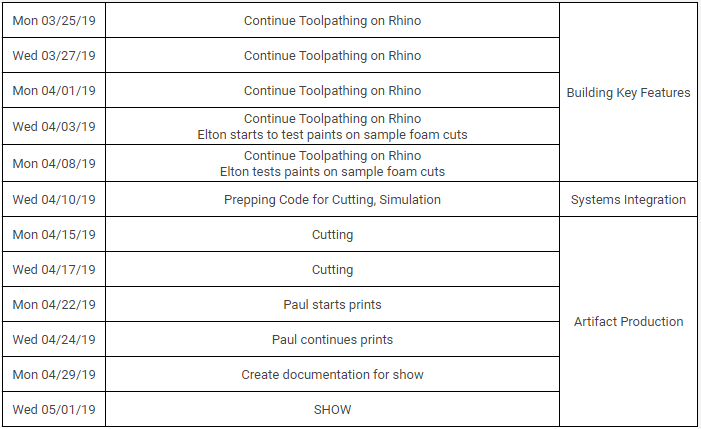
Kevin is working on the tool paths in Rhino and once he is done, we will try to apply the same algorithms to the final image Paul wants us to carve. Then we will runs simulations to ensure no collisions and then hopefully carve on a full sheet.
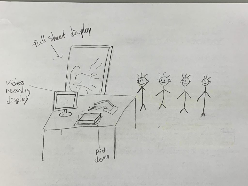
Final Show Vision
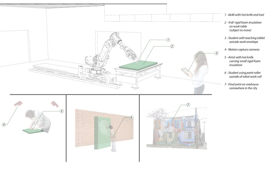
For the live presentation we want to display the full size carvings/prints and also have a small scale demo, maybe with a 1’x1′ print block. We’d like to have a multi-block color print or something beyond just outlines for the smaller print. We will have videos playing of the robot carving at the foam since we won’t have the actual robot, and display the hot knife setup that Paul and the robot used.
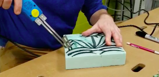
Paul appeared to have an easy time transferring his woodcarving skills to foam. He drew a flower on a block of foam and went to work.
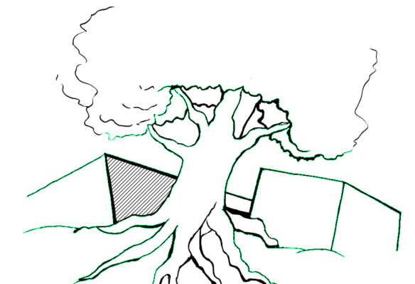
We weren’t able to MOCAP his motion since we hadn’t created a mount for the reflective spheres yet, so Paul drew up a quick picture of a tree and some cubes for us to experiment on before he left. We took the scanned image and converted it into vector graphics before dropping it into Rhino to see how the robot arm pathing would look.

It was incredibly messy. The scan captured way too much detail in the drawing, and Rhino interpreted every little bump in the lines as a new “path” for the robotic arm to follow. We ended up with a few hundred strokes just for minor detailing in the image, so we decided to simplify the image significantly. We also used a smoothing function in Grasshopper to remedy the tiny bumps in the final drawing.

Since we had to cut out an inverse in order to make a printing piece of foam, the generated pathing avoids the outer edge of each line and enclosed body.
Since we’re trying to extend and expand on what Paul can do artistically, we created a Python program that acts as a pattern paint bucket. Much of the detailing of Paul’s work comes from filling in white space of an outline, and enhances the drawing dramatically. The program reads in patterns and a main image, and the user decides which regions should have which patterns. Clicking on the display’s regions fills them in, and the edited picture is exportable into vector format. Paul can use this to decide what parts of the final carving he would rather the robot do.
We’ll ask Paul what kinds of patterns he wants, as well as any other edits he might want to see done to the image. Currently, we just have a striped pattern as a proof-of-concept for the pattern fill.
This program is not integrated with the RAPID code generation yet; currently the picture has to be manually converted to an SVG after the program changes the image, and then processed into Rhino. We’re working on automating this process so that everything after the scan and artist-selected patterning will be automated.
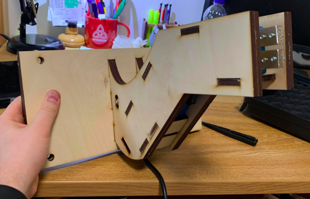
On the physical side of our project, we’ve created a mount for the tool and the foam block. Using one of the orange robot tool plates, we mounted two laser-cut pieces of wood to hold the hot knife in place with a system of pegs. The hot knife can be easily removed with a wrench, allowing Paul and the robot to collaboratively share the knife without having to recalibrate the tool’s location with respect to the arm every time it is dismounted.
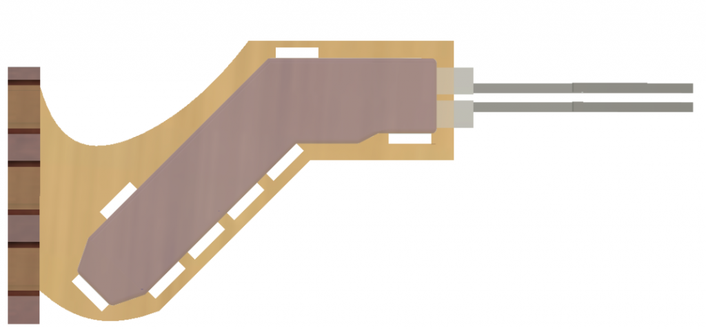
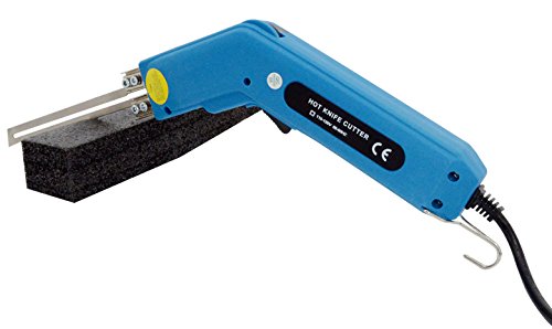
We still had a manufacturing constraint that the hot knife couldn’t be turned on for periods longer than ~30 seconds safely, for fear of the transformer blowing out or the knife itself bending out of shape. While a pneumatic trigger would work, re-prototyping another hot knife mount would have taken too much time. Garth told us about PulseDO, a command in RAPID that can turn on and off the power supply. We plan on pulsing the power to the tool to make sure it doesn’t get too hot, but for now we can manually toggle the power from the control box.
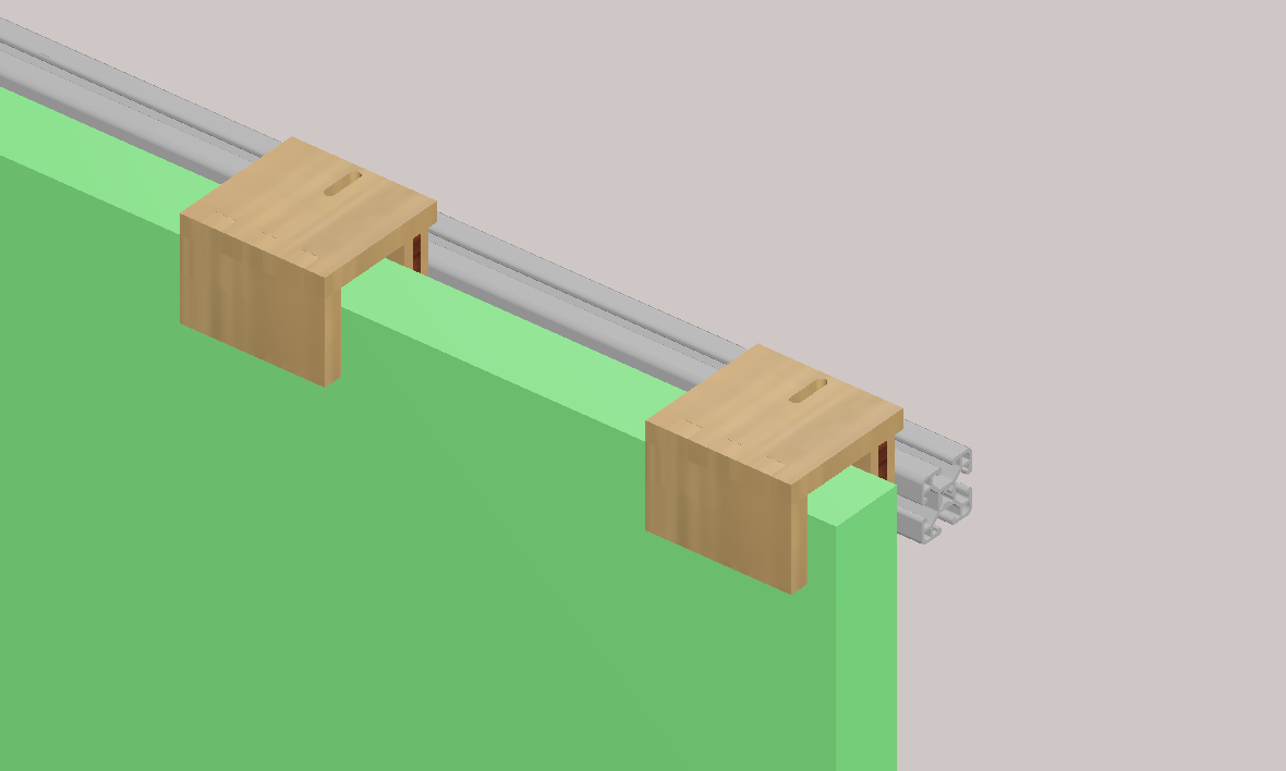
We created a quick script in RAPID to test how well the robot arm could wield the hot knife. After a period of pre-heating, the robot had no problems cutting through the foam, even during very deep cuts. However, we realized that some of the pieces of foam would cool and re-stick in their slots after cutting. We settled on mounting the final foam block standing up, so that any cut-out pieces of foam would just fall out of their slots. We designed a CAD model of the mounts and assembled the laser-cut final pieces.
Reflection on next steps
Currently our prototyping runs pretty smoothly. The only parts that have to be done manually and can be automated are scanning the work that Paul wants to render in the foam, channeling the output from the program into Rhino, then exporting the RAPID code to the robot. After Paul makes his design choices, the process should just automatically spit out RAPID code to work with, minimizing the manpower required to perform the intermediates. But that’s a later improvement.
Currently we have no pattern templates from Paul, which are essential if we want to apply his chosen textures onto a picture. This would be best transferred through some kind of picture file that could be repeatedly tiled, and the Python program would have to be modified to include a number of constraints on where the patterning goes, i.e. density, separation, border size. With the base program done this wouldn’t take too long.
The hot knife tool we attached to the robot arm can cut at any radius up to ~2 inches, but the tool pathing generation in Grasshopper does not utilize this potential of the knife. By adding a depth-to-width cutting awareness depending on how wide the perpendicular is, we could cut down on carving time, as well as get a more accurate trench between converging lines. This could also be adapted to cut using a different edge for large swathes of blank foam, which require less accuracy and more sweeping cuts.
The tool’s mount is pretty stable for now, as is the foam mount. Since we want to carve on a standing piece of foam so that the scrap pieces fall out, the foam mount is essential. We need to experiment with the gaps sizing, but with 4 mounts the setup is stable enough to carve on.
Finally, we’d like to give Paul more options with regard to modifications to the art he would like to carve and the art he’d like the robot to carve. Right now we have patterning and straight line down, but we need to consult with him about tasks he finds difficult in the process that could be automated. Alternatively, we could look at hybrid art pieces that have strokes that are intended to have a different style in the way that they’re carved, allowing Paul and the robot to work together on one canvas.
]]>
In supporting Paul’s move to faster and larger print setups, we wanted to enable his prints to maintain their same level of detail even in a blown up scale. He suggested doing large prints on the sides of abandoned buildings or empty parking lots which is doable with adjustments to his process. Large carvings would take a lot more material and time especially if using wood, at the same time making it difficult to set up printing on uneven and large surfaces. We think using foam sheets and a hot knife as the tool would enable the large-scale carving of surfaces.
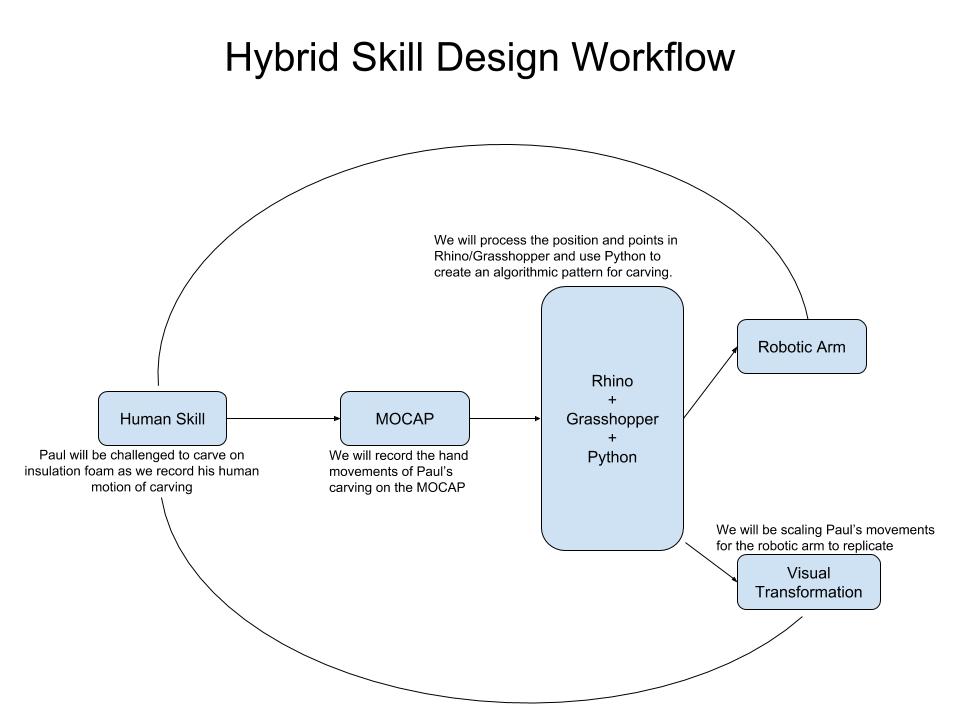
Our project aims to get a mocap of Paul using a hot knife tool to carve into foam, then program a robotic arm to use his technique on a drawing. We also want the solid outlines of the drawing to be filled with repeating patterning programmatically, on a finer level than would be allowed for a scaled image. Ideally, we’d have multiple patterns supplied by Paul so we can add whatever he thinks is best on the front.
In the end, we should have some programs which are able to take in a mocap of a technique and replicate it at whatever scale we’d like to render a drawing. These sheets could be used repeatedly by Paul on any surface he desires.
After talking to Paul on Monday and considering our options, we went ahead and put in an order for a hot knife. While this isn’t Paul’s usual domain, his adoption of a new tool and new technique should reflect his previous technique of woodcutting. We will mount markers on this cutter and proceed with the tool modelling. The robot arm can then proceed through a similar technique as recorded from Paul.
Our process is as follows:
- Place the markers on a visible area on the tool so that the MotionCapture Cameras can detect the markers.
- Collect 5 seconds of continuous data points
- Export data into Rhino/Grasshopper
- Synchronizing data to work space
- Map saw representation to the data
Looking at the final result, we can extrapolate the following:
- The push motion appears to require more force than the pull, which helps us realize that the cutting part of a hacksaw is a result of the pushing motion
- The hacksaw’s motion shakes horizontally, as it is difficult for humans to have precise streamlined motion
- The cutting motion likely results in more wood being removed from the ends/edges of the material because of the rocking motion
- The hacksaw appears to have never left the wood which suggests that it can also cut on the pulling motion
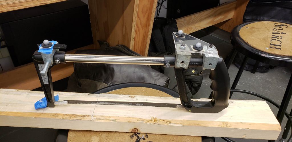
This also makes visible other aspects of the tool. While cutting a deeper channel into the material would stabilize the tool, initially, it’s left to human skill to keep the tool properly positioned. It does help that the blade of the tool has inherent flexibility, which can make the cutting process more forgiving, skill-wise, since you don’t need to keep the saw oriented parallel to the cuts all on your own. The lateral noise should still be a marker for skill, since a trained individual might be able to reduce that sway as extraneous movement, or at least cut much faster with the same amount.
]]>