System objectives
Starting from the traditional folding technique of pleating, our system facilitates the creation of pleating patterns through a 2D interface in Rhino. Pleat designs can be rendered in the physical world by printing the crease pattern on paper or can be rendered virtually as mesh models in Rhino or other modeling applications.
“Complete Pleats” by Paul Jackson served as the primary reference material regarding pleating techniques. Amanda Ghassaei’s online origami simulator was used to simulate the fold patterns created in Rhino. Translating between Rhino and the simulator employs the.FOLD format.

The book 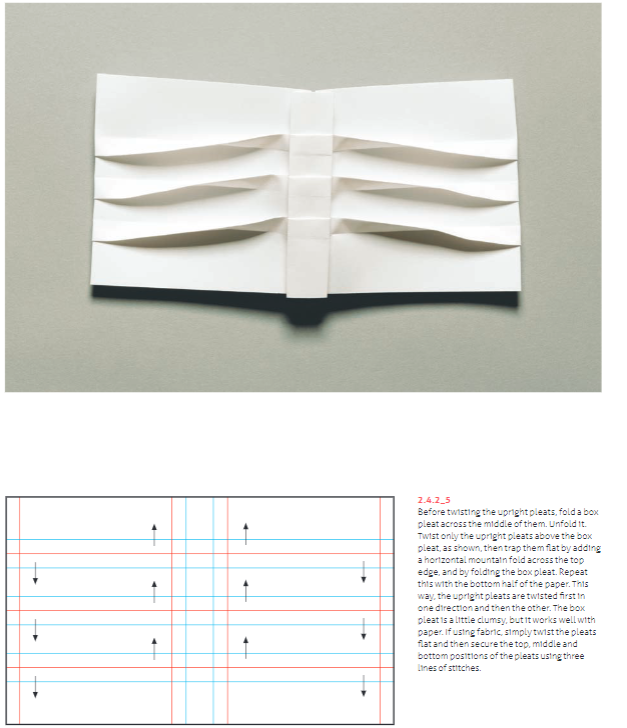
Basic Folding and Pleating technique
After creating the core pipeline which translates 2D line drawings from Rhino to 3D dynamic folded forms in the simulator, each team member aimed to extend the tool and create unique artifacts from individual workflows.
Core system
The core system has three primary components: the Rhino working area, the grasshopper script that translates the Rhino geometry to. Fold format and displays the mesh of folds, and the online origami simulator created by others.
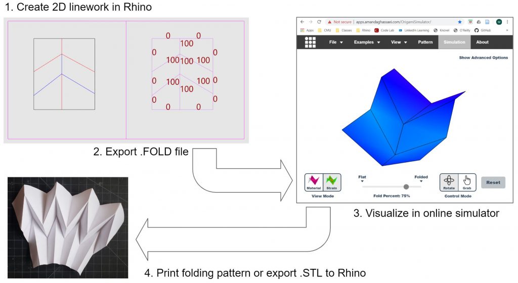
Core Workflow
A designer creates line geometry in the Rhino work area using layers representing each type of fold supported by the origami simulator. While the type of fold is set by the layer, the angle of the fold is set explicitly by using the line object’s “Name” property.
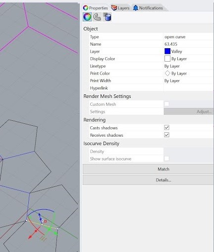
Properties of each curve 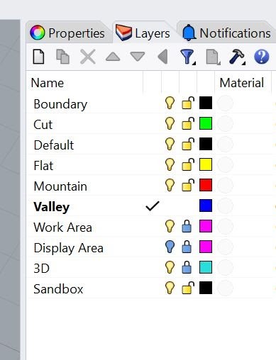
Different layers
At any point, the designer can visualize the design by saving a .Fold file of the design and uploading it to the simulator, allowing for quick iteration between 2D and 3D representations. Concurrently, the designer may explore the design by folding physical material, either freehand or from patterns printed from the digital model.

Individual workflows and artifacts
1. Curve to Pleated Surface Tool
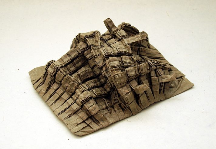
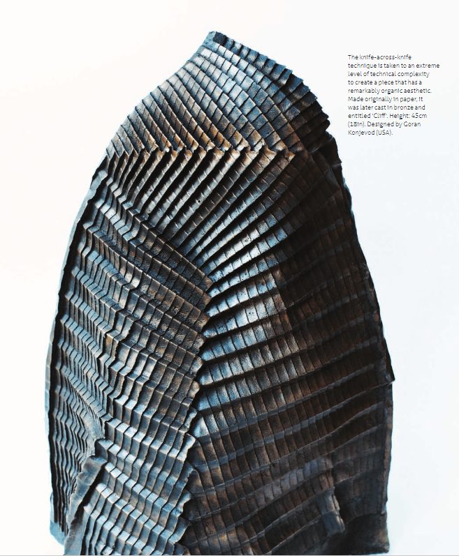
By utilizing the primary Rhino to .Fold file pipeline, we are able to easily translate content created in the Rhino workspace into the online simulator to visualize the creation. I have decided to utilize this tool to experiment with pleating patterns to create a dynamic curved surface. As seen in example projects (figure 1.) simple pleating patterns can be freely manipulated after having been folded to create dynamic forms that are more exaggerated than their folding pattern initially lets on. This exploitation of a pleated form highlights the respective strengths of both digital and analog making within this pipeline.
Digital Manipulation of Input Geometry:
Keeping in mind the possibility of manipulating a pleated material, a target form is created in the Rhino workspace. In this pipeline, the target form is a freeform curve created by the user in elevation. The goal of the pipeline is ultimately to approximate this freeform curve though the assignment of pleats to describe it.
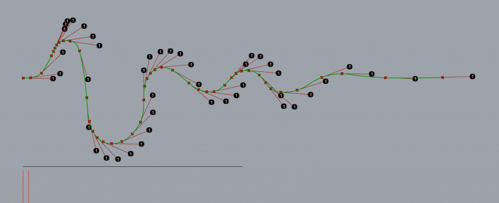
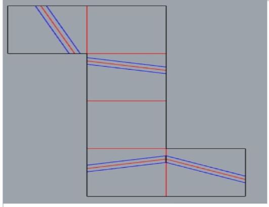
To begin, a freeform curve is drawn to the liking of the user. Then utilizing a grasshopper script, a series of points are assigned to the curve based upon the degree of curvature. (Figure 2.) The areas along the curve of more severe curvature are assigned a higher density of points to describe it. The descriptor points are grouped into two categories: positive slope and negative slope. These two types of points will get assigned different types of pleats described later in the process.
Next, the curve and its newly assigned points are unrolled along the X-axis. Each point represents the future location of a pleat. In this example, the points with a negative slope are assigned a knife pleat that steps down, while the points with a positive slope are assigned a knife pleat that steps up.
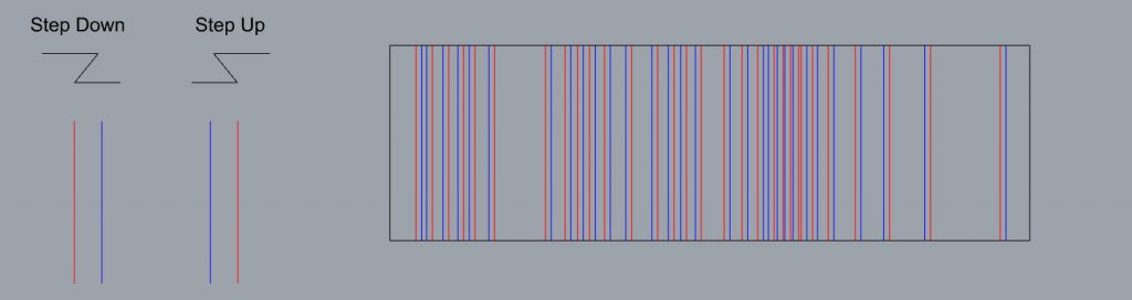
Once assigned along the X-axis, the fold pattern resembles an intricate patterning of mountain and valley folds. (Figure 3.) However, this pattern can be easily visualized utilizing the online simulator. This portion of the pipeline utilizes the primary “rhino file to .FOLD file” export function that is shared between each pipeline developed within our group. Once the file is exported from Rhino to the simulator, we get a sense of how effectively this pipeline was able to approximate the input curve by assigning points and pleats.
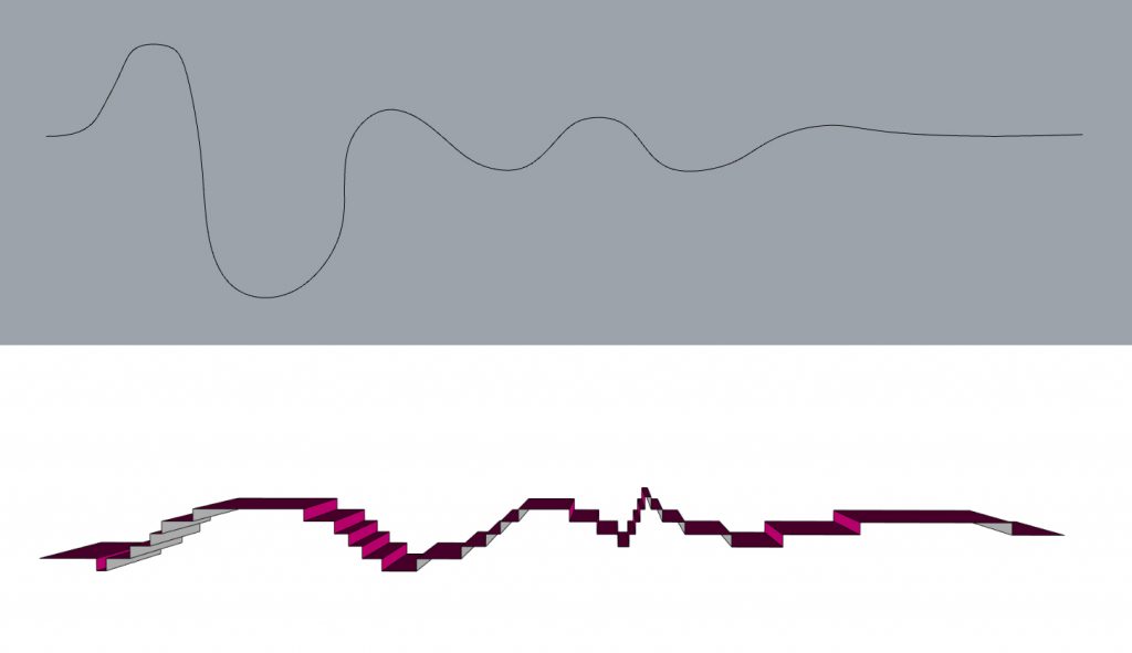
As seen above, the knife pleat fold lines are engaged at a 90-degree fold which maximizes the vertical distance change. We can begin to see the input curve represented in the simulation, however, it is not nearly as dynamic as the input itself. (Figure 4.) This is where the analog folding of the pattern will take the form to the next level and truly start to resemble the original input or something derived from it. One of the strengths of analog folding of the pattern is the ability for the user to intuitively vary the angle at which each fold is set. With the simulation, each fold is set to the same degree. When folded by hand, the folds can be stretched, manipulated, and compressed easily at varying degrees to further accentuate the form.

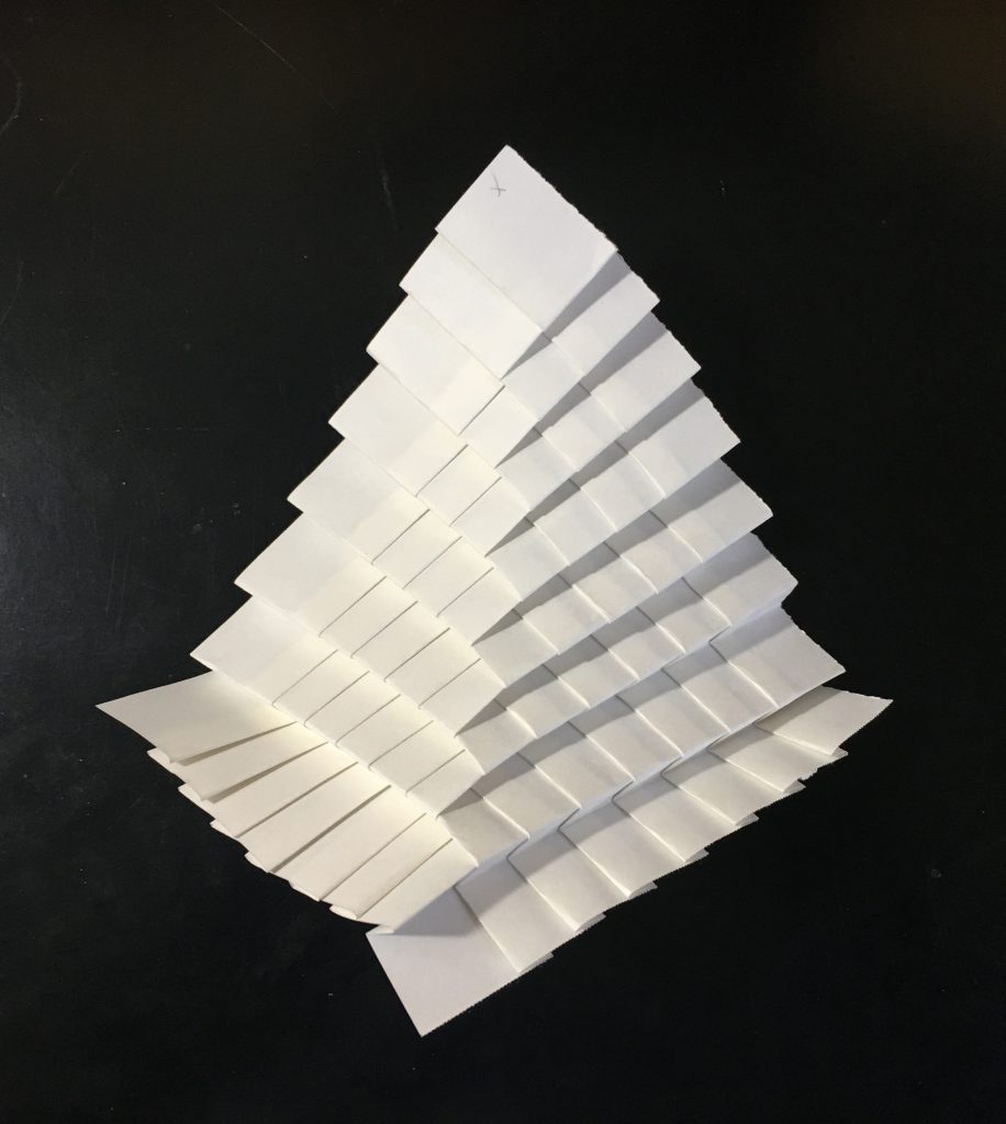
You can see above that I have accentuated the curve past what the simulator suggests. To create a more interesting form, I have stretched open the pleats along the peak each curve, while minimally altering the pleats in between. (Figure 5.) A single valley fold along the back edge allows the form to keep its shape and become more expressive by providing rigidity.
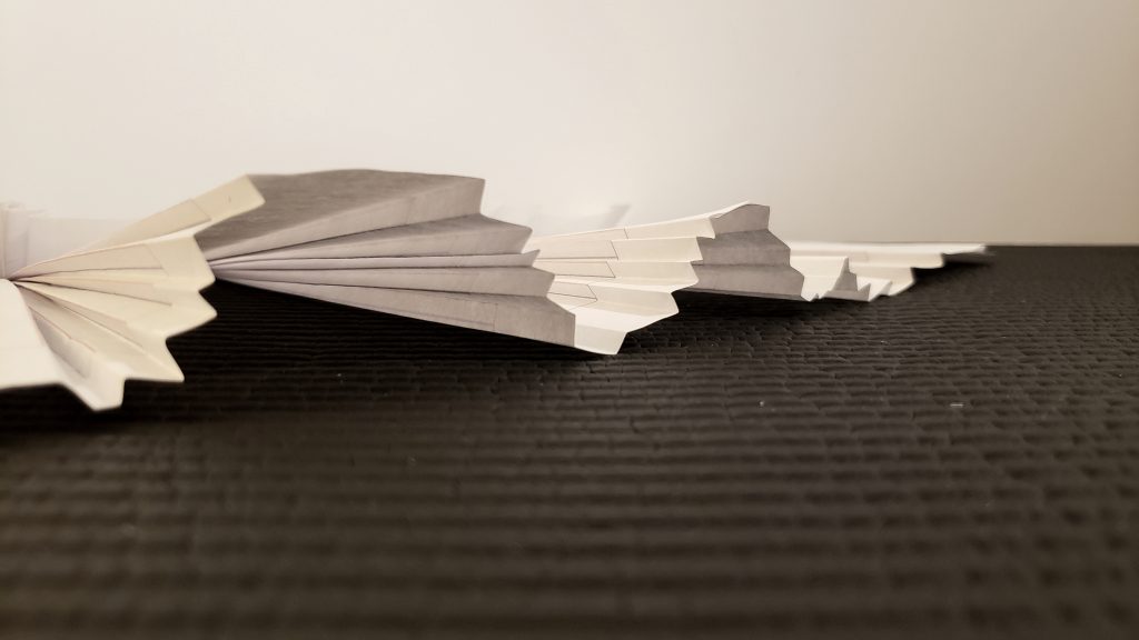
With this workflow, the creator has the ability to create a dynamic profile for a material knowing that the pleated form will result in a similar shape. From there, they can manipulate, fold, and twist the form into something different from the original input. This application could be utilized from a scale as small as paper folding, to something as large as inspiring the roof form of a building. For a further and more detailed demonstration of how this portion of the pipeline functions, see the video below!
2. Pleat intersection workflow
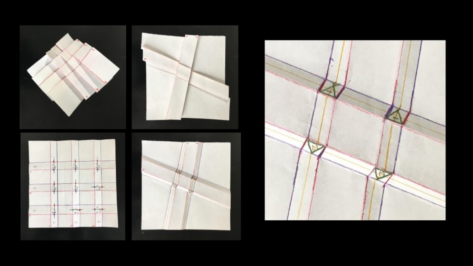
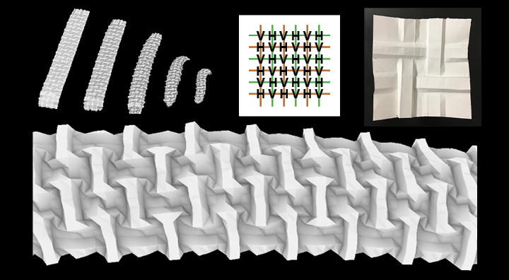
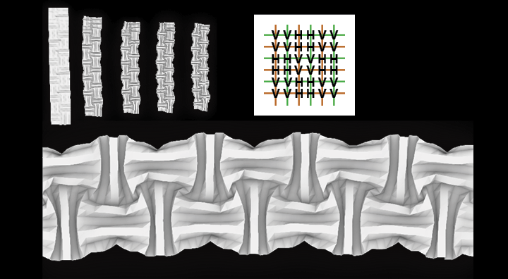
This workflow introduces an alternate representation method to the core tool. In addition to using single lines to represent individual folds, single line representations are expanded to include pleats of multiple folds. Knife folds, as shown in the Core Workflow images, are used to explore pleat intersections. Rhino layers for left and right-hand knife pleats are added to the model for the designer’s use. Critical to representing pleats of multiple folds is understanding the pattern of the resultant folds at an intersection. The image below explains how the sequence of creating the intersecting folds impacts the pattern of the folds at the intersection. Because the sequence of each intersection is required to be defined, the second avenue of input is opened for the designer to manipulate.
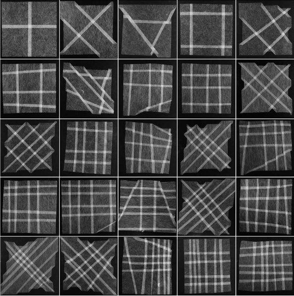
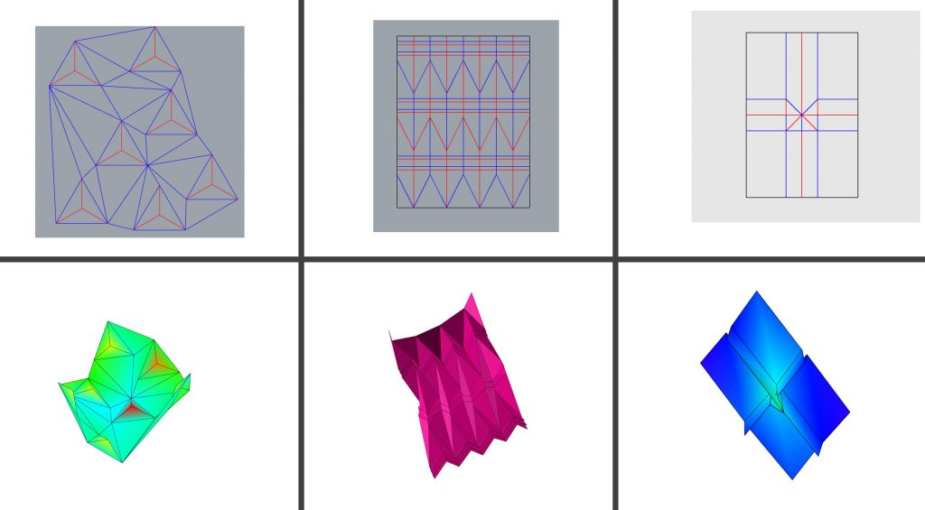
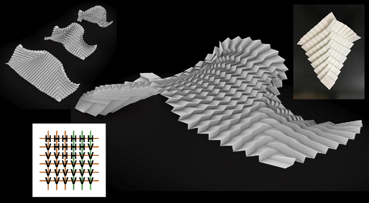
The work below introduces the formal possibilities that can be explored when intersecting knife pleats. The order patterns were created using simple looping algorithms. However, the nature of this intersection representation affords many other possibilities to assign order values. As is seen in the examples shown below, the interplay between even simple variations in the knife fold hand and the sequence order creates a broad variation in the formal and performance qualities of the 3D object.
3. 3D Pleating
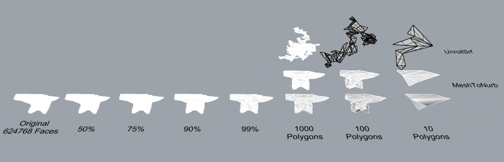
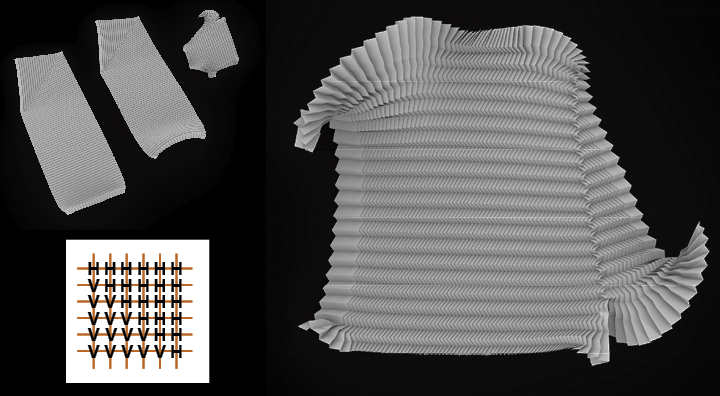
This workflow introduces a way to pleat on a 3D object. This workflow adds a 3D possibility to the core tool. In addition to manipulating solo 2D folding patterns, this workflow provides an opportunity to deal with 3D folding patterns for users. The users can create their own 3D objects and add folding patterns on their unrolled flat surfaces. Just as the figure shown below, a cube can be pleated pretty nicely.
Pleat on unrolled surfaces 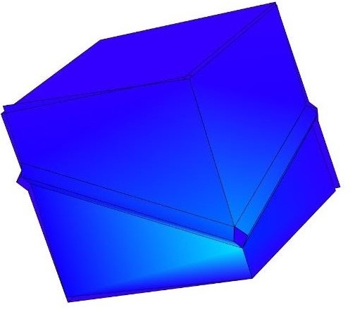
Simulation result
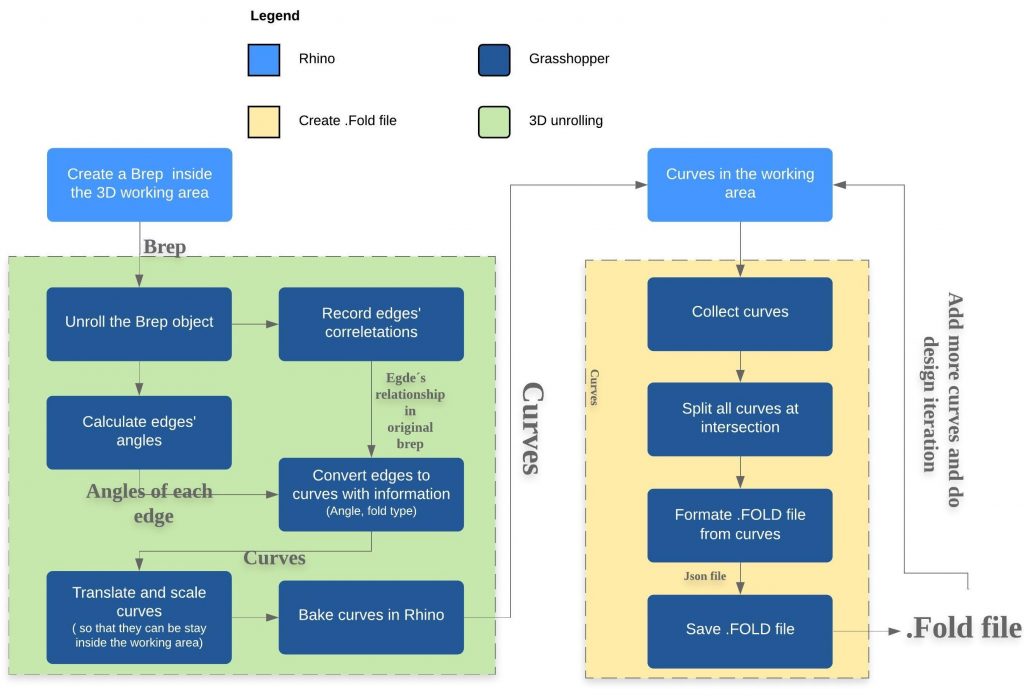
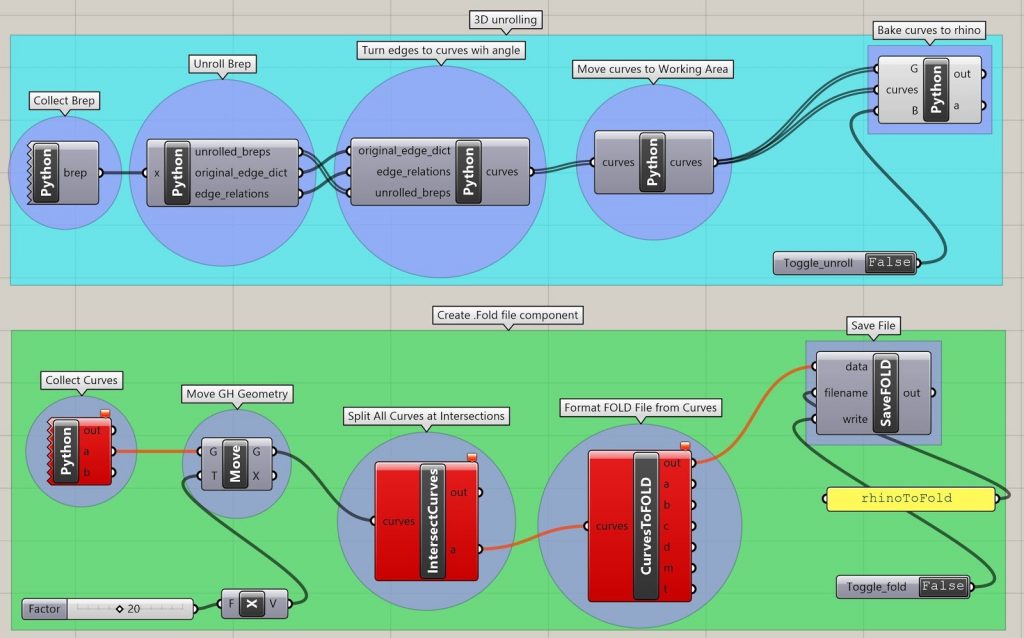
The following graph shows the 3D pipeline workflow. The user first creates a 3D object. The pipeline then automatically gathers this 3D object and unrolls it to a flat surface. All the edges’ relationships and angles are saved as the core workflow standard. The flat surfaces are then translated and scaled so that it can be inside the “Working Area” which can then connect to the core workflow. The last step before using the core workflow is to bake these edges from grasshopper components to rhino components. The user can then iteratively design on the flat surfaces and then see how it goes in the fold simulation.
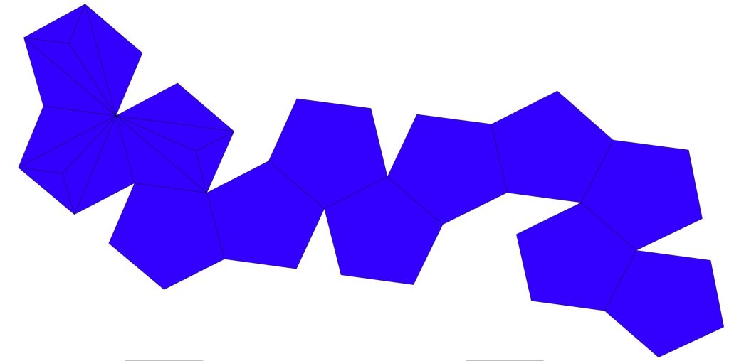
The following video shows the automatically unroll part. It can handle most types of 3d objects. The following video shows this scrip unrolling cube, polygon solid, and an egg-shape 3D object.
The following video shows the actual pipeline to pleat or add new folding pattern to a 3D object, which is a dodecahedron. This 3D object is first unrolled as flat surfaces. The user can then try to add mountain or valley fold to these surfaces. After several design iterations, the user can view the result through the simulation environment.
The following pictures show the fabrication result. The user can create the actual modified 3D object using paper.
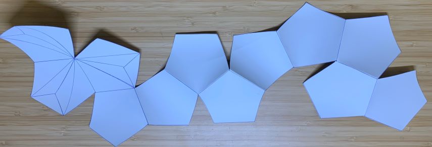
The pleated 3D object in the simulation 
Fabricated result
Reflection
Much like the application of traditional pleating techniques, the rhino to .FOLD pipeline which serves as the core of our project proves to be a useful tool for a wide range of uses. Shown by the three distinct adaptations above, the pipeline can be manipulated as a parametric pleating design tool, 3D to the 2D form builder, and curve simulation tool. Surely there are many integrations of the tool that are yet to be seen, but that’s what makes it so powerful.
Exploration with the tool resulted in a need to balance digital and analog modeling. Questions stemming from these explorations circle around the possibility of how to create a feedback loop between the digital and physical realm. How can one introduce existing pleating or geometry to the rhino workspace from the physical world and continue to develop it through digital means? Once a design is completed and physically made, is there a way to capture this development? While there are a number of directions to explore, we know that our Rhino to .FOLD pipeline represents the “middle link” in a chain of design exploration. Exciting possibilities only need to be imagined using this digital twist on the traditional practice of pleating.