Design Example: Open Molded Soft Silicone Actuator
This sample demonstrates the design of a basic silicone pneumatic-net actuator [R26] fabricated using a pair of open molds.
The SolidWorks model files and STL 3D printing fabrication files may be found in the SolidWorks/finger-test-1 folder, or may be downloaded as a single file as finger-test-1.zip.
SolidWorks Design Workflow
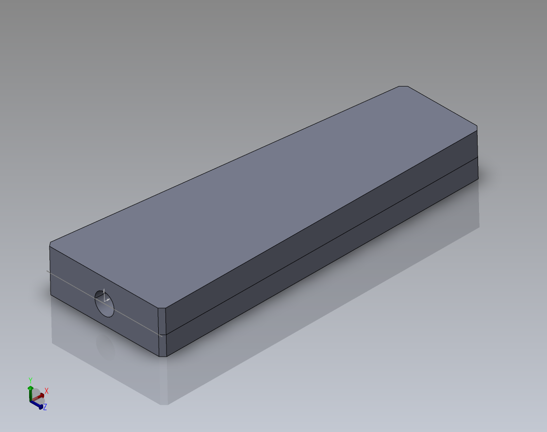
The part was modeled with internal inflation cavities. The outer faces are flat as they will be formed by the open top of each mold.
A splitting plane was selected along the centerline of the tubing port. The split surfaces should be concave with no overhangs, as they will be each formed by a mold. Each half was saved into a separate (derived) part file.
For each separate mold (top and bottom):
The mold blank was modeled as a block larger than the part to fabricate.
As assembly was created using the mold blank.
The fabricated part was added to the assembly with mates to align inside the mold part.
The mold part was edited in the assembly context and Cavity feature added to subtract the part.
The mold part was exported as a STL for fabrication.
Please note that the design is associative: changes to part geometry will propagate to the mold cavities when the mold assembly files are reloaded and rebuilt, and new mold STL files may then be exported.
Other Views
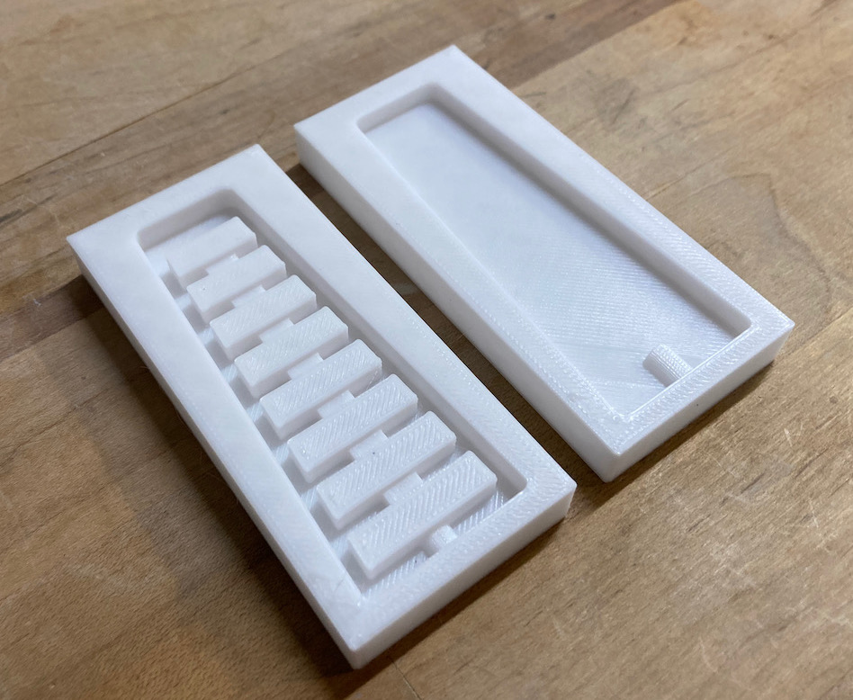
Photo of 3D printed molds for the part. Note that this is not a two-part mold: each part is fabricated separately, then bonded together. The featured mold surfaces are attached in the final part, and each open surface is on the part exterior.
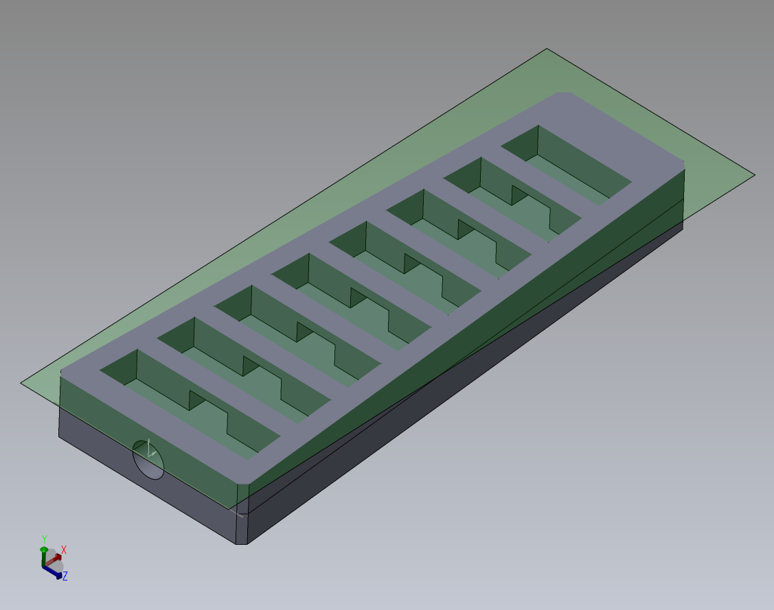
Rendering of cross-section showing the width of the internal cavities.

Rendering of cross-section showing the height of the internal cavities.