
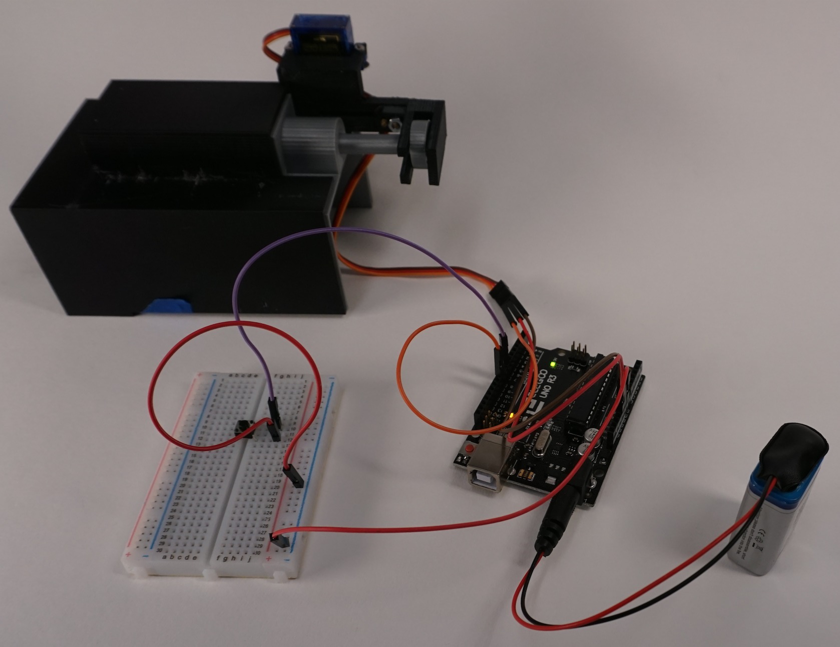
The full mechanism with all of the modular components shown.
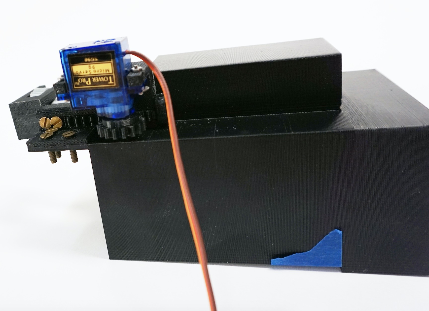
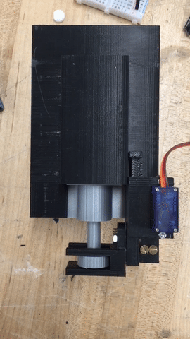
The actuation is driven by a servo which turns a rack and pinion mechanism.
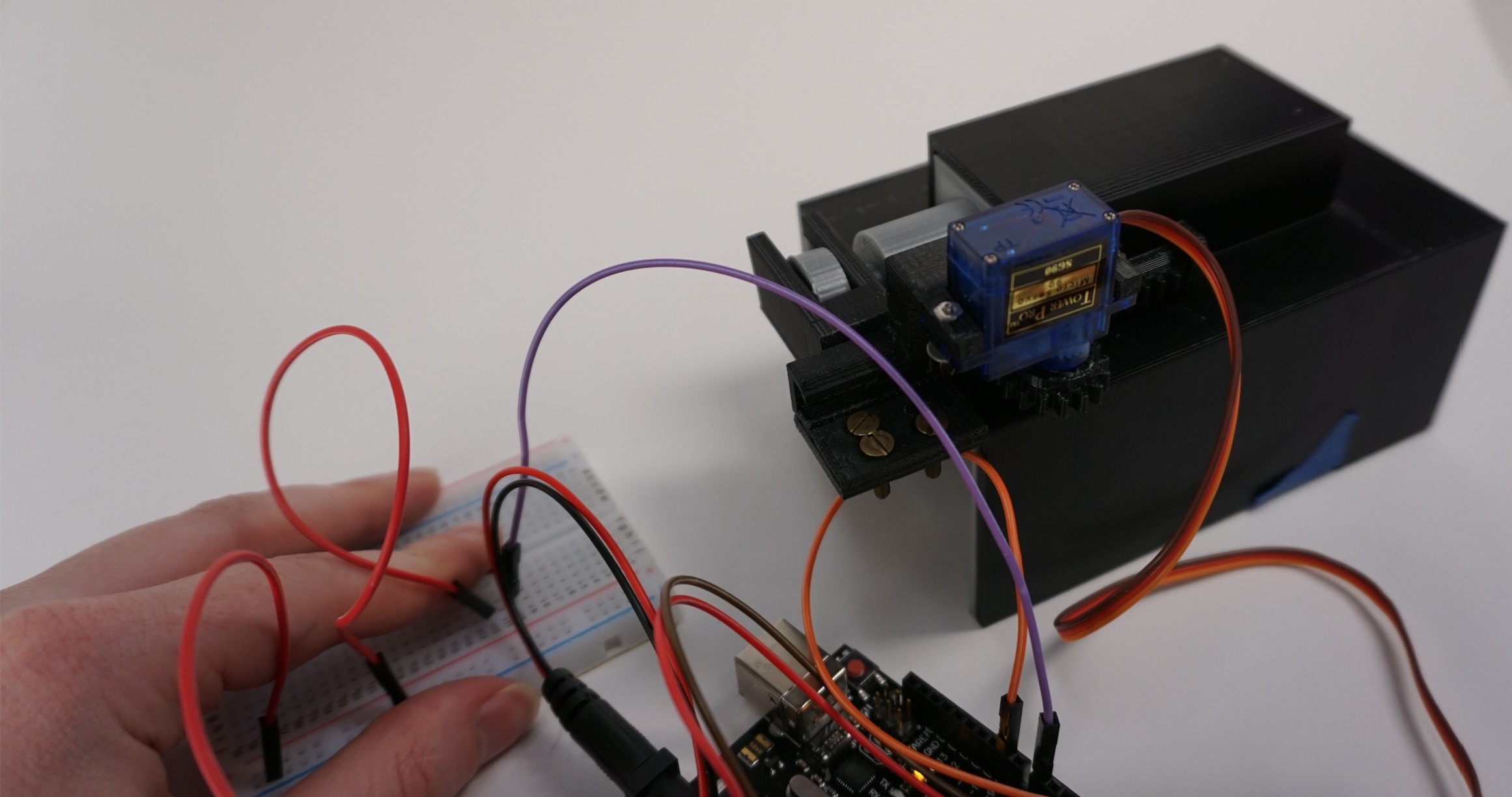
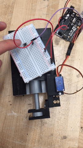
The servo of the switch is triggered by a push button. For the final device, the servo will be triggered by a photoresistor.
Video of device in action.
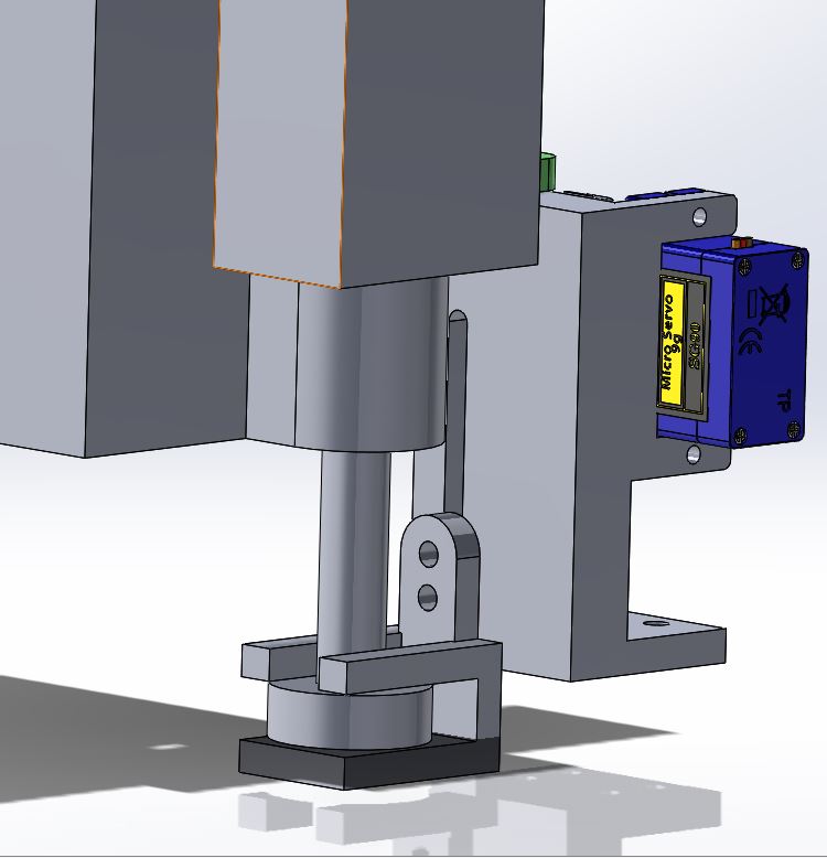
Our device turns “on” and “off” a model of Joanne’s linear toggle switch. The servo turns the gear 160 degrees and the rack meshed with the gear converts that rotation into linear actuation. A grip for the toggle switch handle is connected to the rack so when the rack moves, the switch is pushed or pulled with it. The user pushes the button to activate the servo.
Process
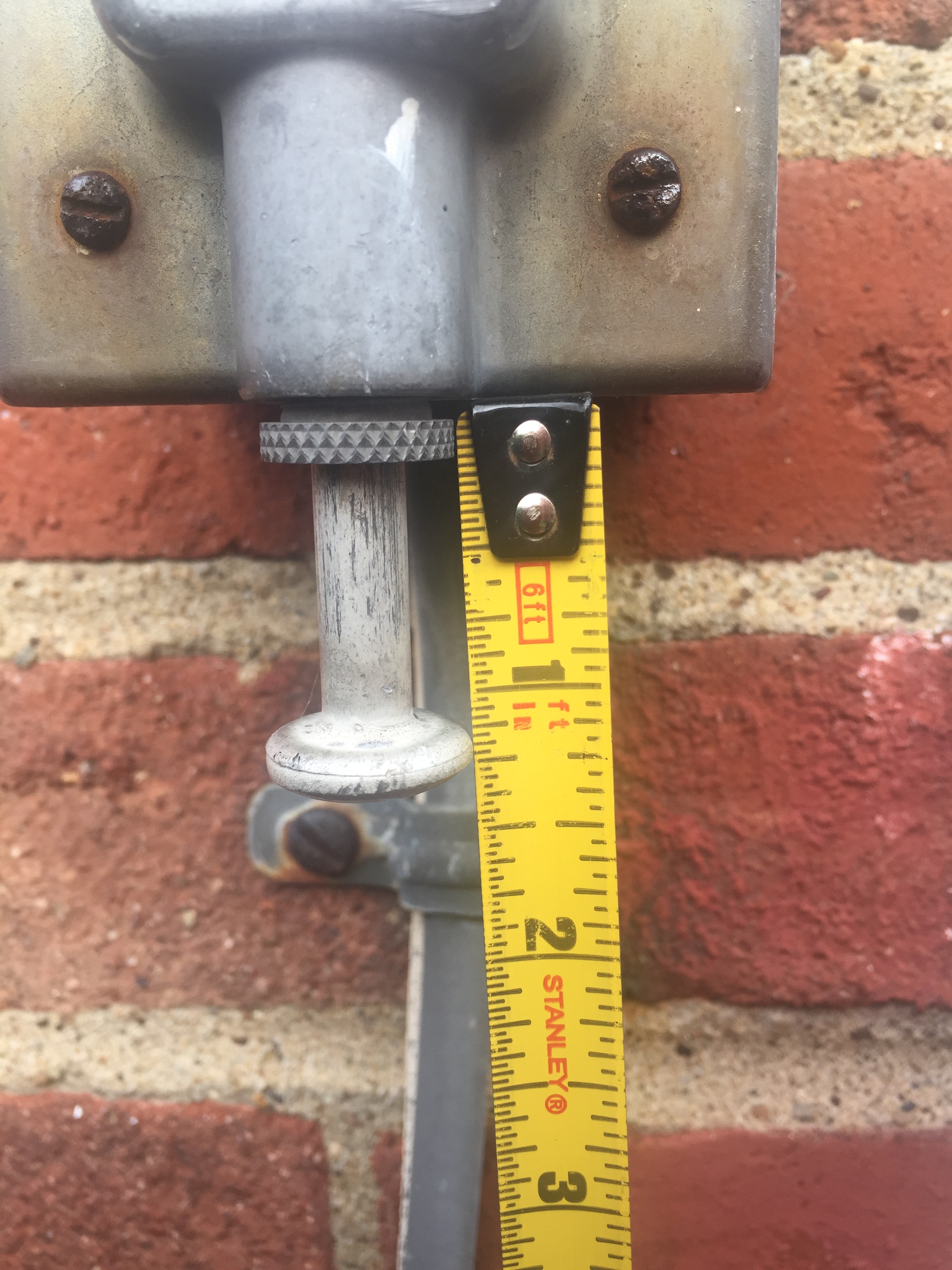
We first needed to take a bunch of measurements of the toggle switch at Joanne’s house.
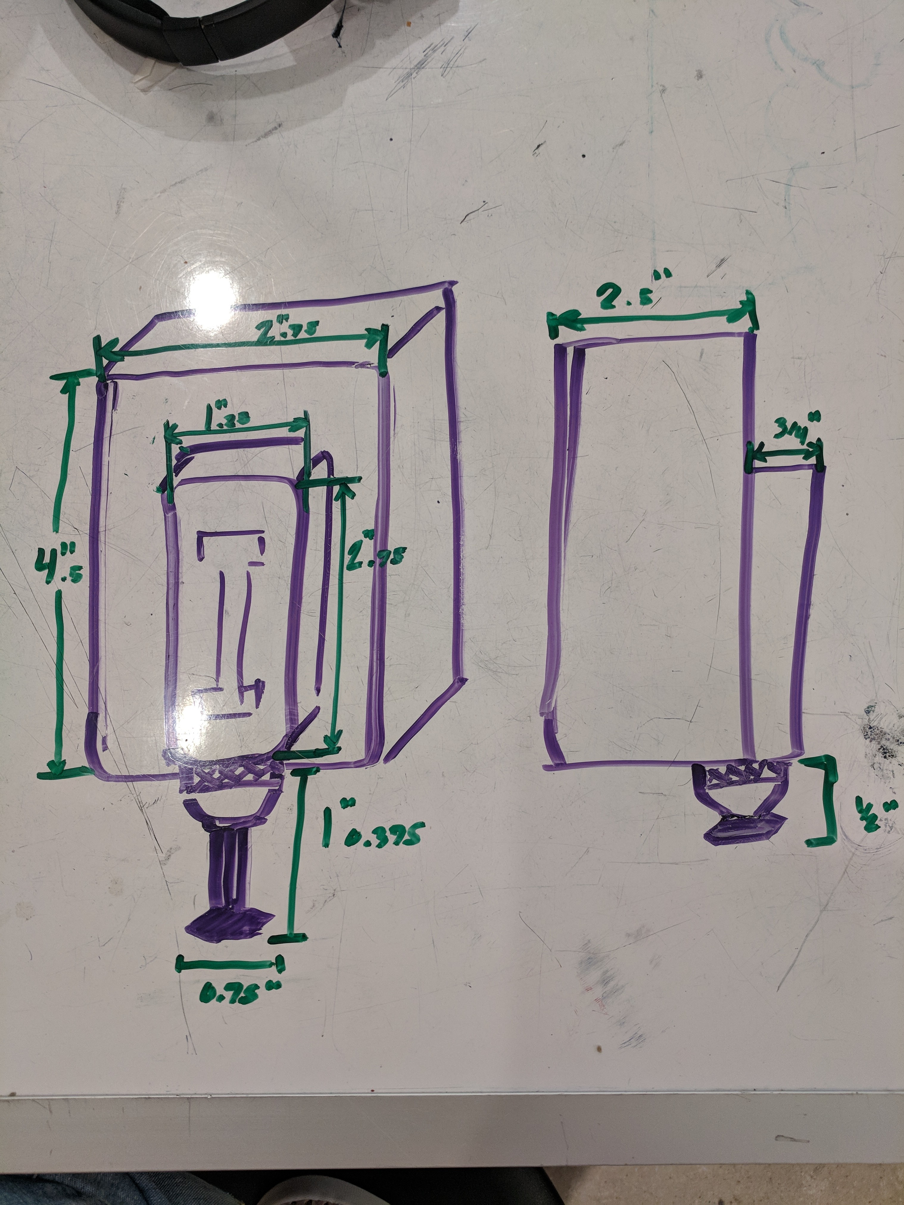
After we had all the measurements we needed, we drew some sketches of the switch box and started generating ideas for what we were going to make to move the switch.
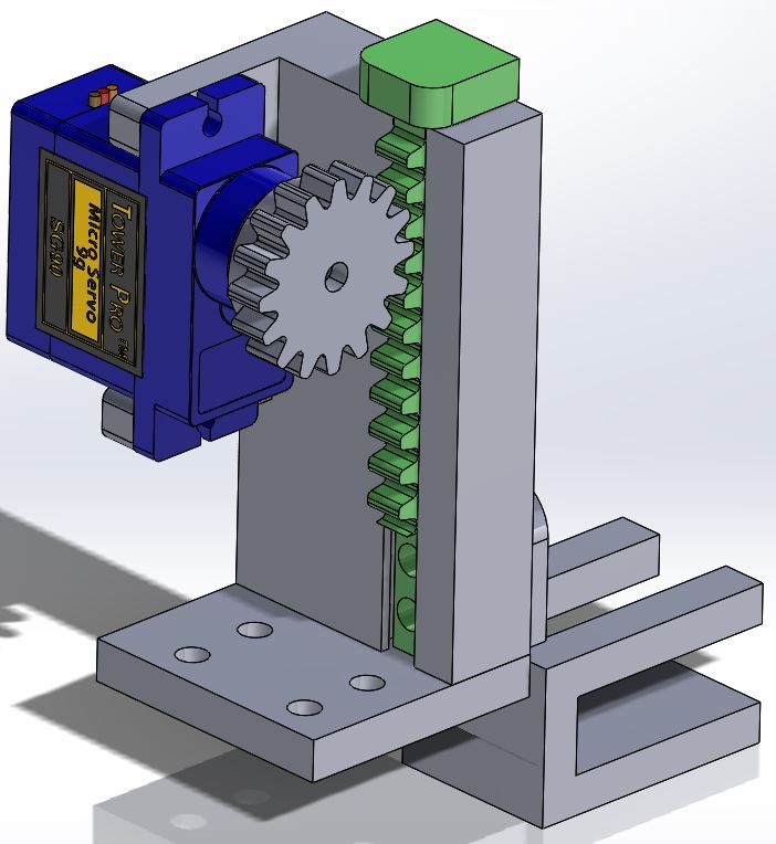
We decided on a rack and pinion mechanism driven by a servo for the actuation. This is the first thing we modeled in SolidWorks. The toggle switch grip is mated to the backside of the rack and we made a 4 bolt pattern on the base to attach it to the switch cover that we will also model.
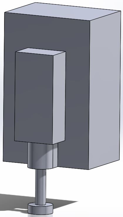
We didn’t originally plan on designing a model of the toggle switch box but we decided that having a 3D model of it would make designing our mechanism easier instead of just going off a two dimensional sketch.
We mated the rack and pinion mechanism with the toggle switch box in an assembly to see where and how our device needs to attach to the box. After doing this, we realized that the 4 bolt holes on the base of our mechanism isn’t the best method of attachment.
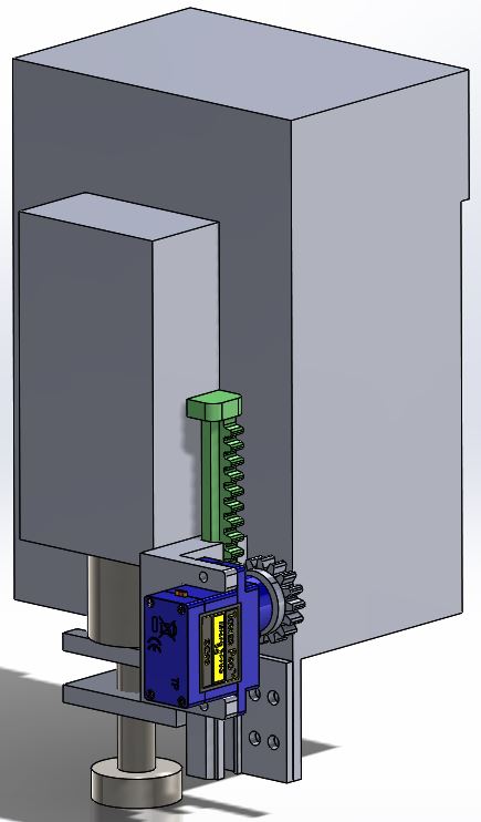
We designed the box cover which will be the way our rack and pinion mechanism is attached to the toggle switch box. The base was removed and a segment of the lateral wall was extruded further for the 4 bolt pattern. The picture shows a full assembly of the box cover over the toggle switch box and the rack and pinion mechanism mated to the box cover. Time to print!
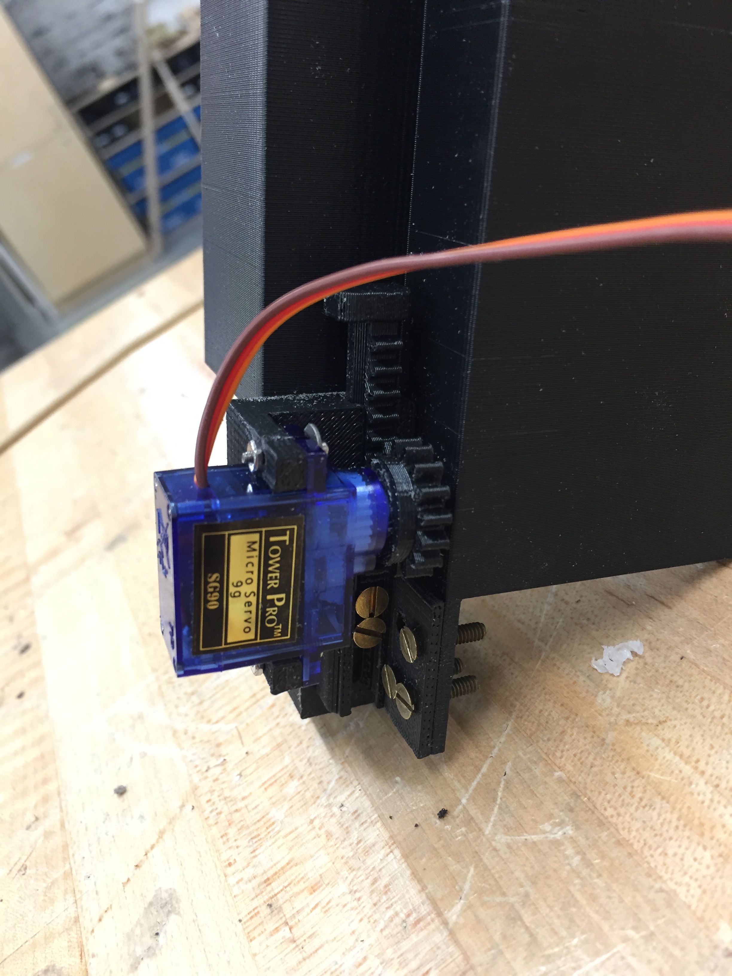
The print came out clean but still required a little bit of sanding to allow smooth movement of the rack and pinion. Most of the parts were connect by a screw. The picture shows a complete assembly of the device that will be attached to the toggle switch box.
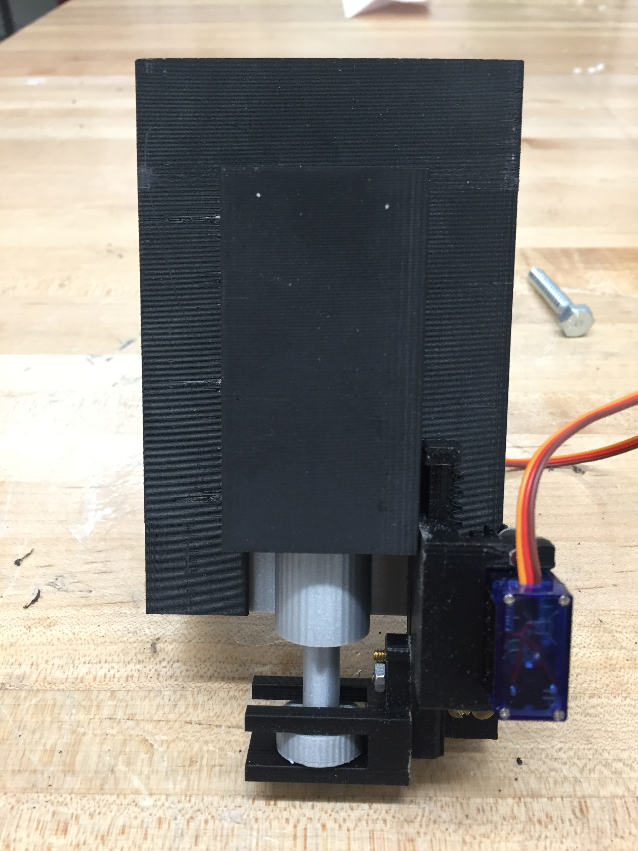
Our device easily slipped onto the toggle switch box and was ready for testing.
We first uploaded some basic servo example code to test the movement of our device. We achieved the full range of linear motion that we calculated for the actual toggle switch box at Joanne’s house. After this all we had left to do was implement a way for the user to trigger the servo.
Discussion
Major CHallenges
In the previous week we gained and subsequently lost a group member. This caused a communication error and the prototype had to be given a button last minute so it could be activated during the interview. This complicated the explanation of the system to Joanne because the presence of a button implied that a button would activate a device. It caused a bigger communication error, as the most important part of the process is that a photocell inside of a front door lamp is the trigger to start the Arduino. So there is no additional button we are adding to her home, she flips the switch inside of her house and the front lamp goes on telling the Arduino to start. The presence of the button confused Joanne so it took longer to explain to her the system. The only challenge with designing our mechanism was that we did not take precise measurements of the toggle switch box at Joanne’s house so for many of our dimensions we had to estimate it. These estimations stacked up sometimes and caused certain features to be misaligned.
The Crit
Overall the crit was a good opportunity to reassure Joanne about the power source and the visibility of the wires. Her commentary mostly revolved around aesthetic of the system and concern about the dangers of the electricity. After we thoroughly explained the system and she understood exactly what was happening she was reassured. We didn’t spend much of the crit critiquing, it was mostly explaining in detail how the system would work for Joanne.
Joannes main concern was the visibility which led to a conversation about the wires and voltage. After Zack reassured her we set a voltage goal of 12 volts as we move forwards. We bonded more with Joanne and instilled a solid trust but beyond that our system is relatively straightforward and there wasn’t too much new. It reminded us of the importance of the weatherproofing but we had already been thinking about that.
We will be ignoring none of her concerns as they were all quite valid, all revolving around visibility and electricity.
Planned Next steps
We will need to guarantee the servo switch is waterproof so we are planning on finding the waterproof servo. From there we will double check with Joanne that she wants the LEDs wired into the system, she made a few comments that could have one of two meanings, concern for the visibility, and/or a desire to not have LEDs. So we will reach out to her for a decision. Aside from all of the small details we will be powering through as we have a lot of voltage and wiring problems left to tackle. Also, in order to assure that our device perfectly fits to the toggle switch we will make another trip out to Joanne’s house with a caliper and take more exact measurements.
Leave a Reply
You must be logged in to post a comment.