
This black box lowers a key when the correct passcode is entered and reels the key back up at the press of a button.
Final Product Images
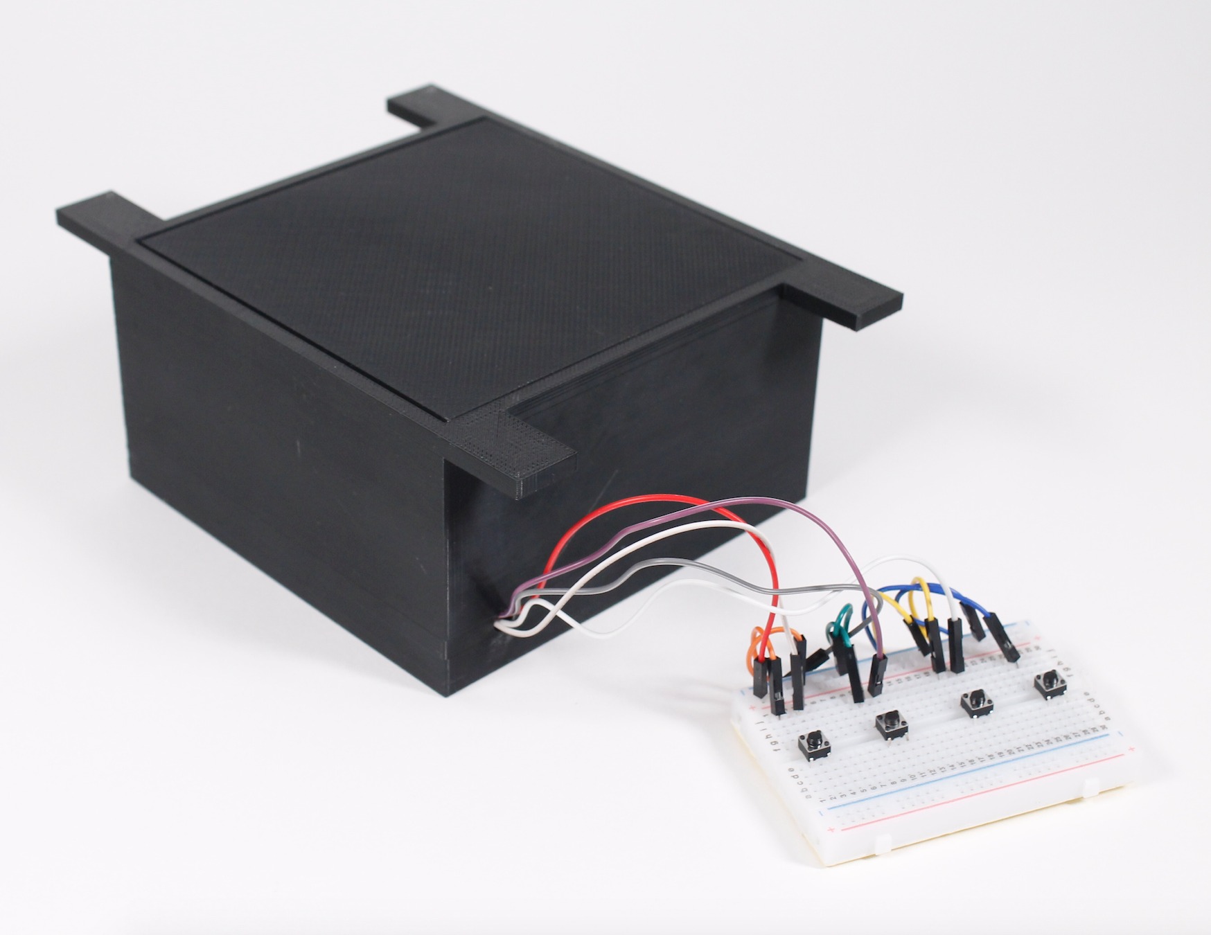
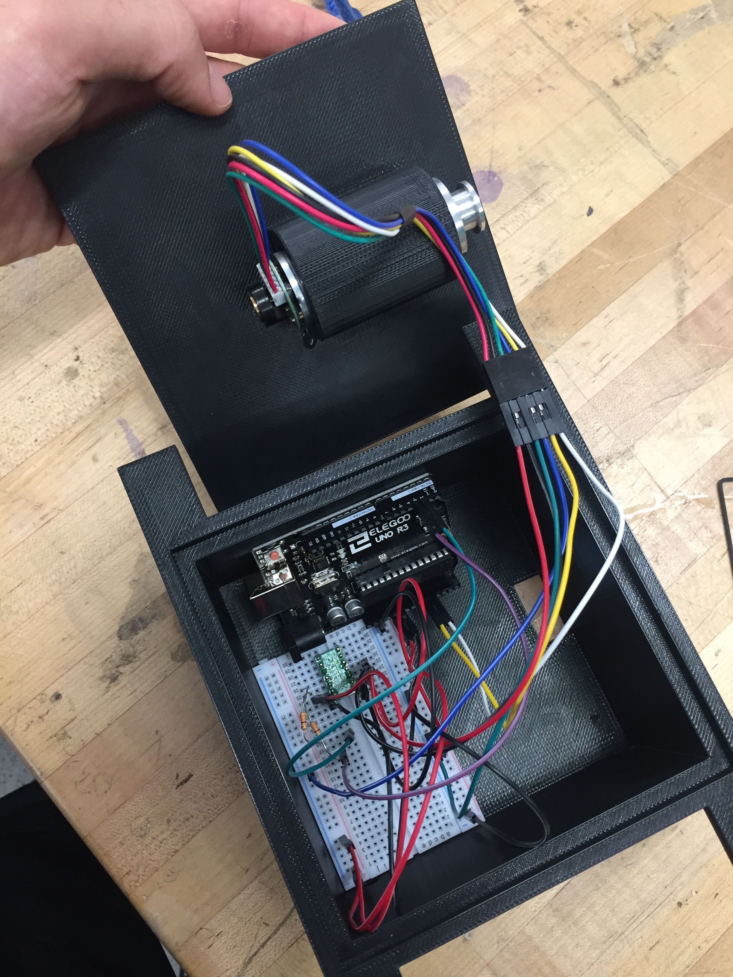
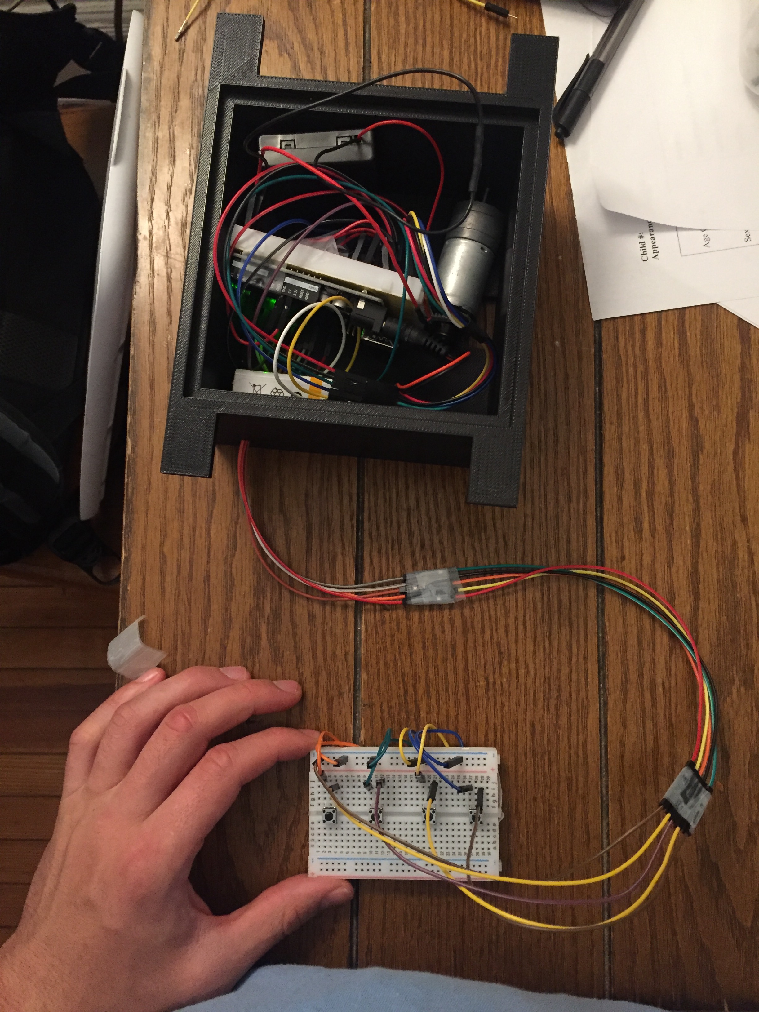
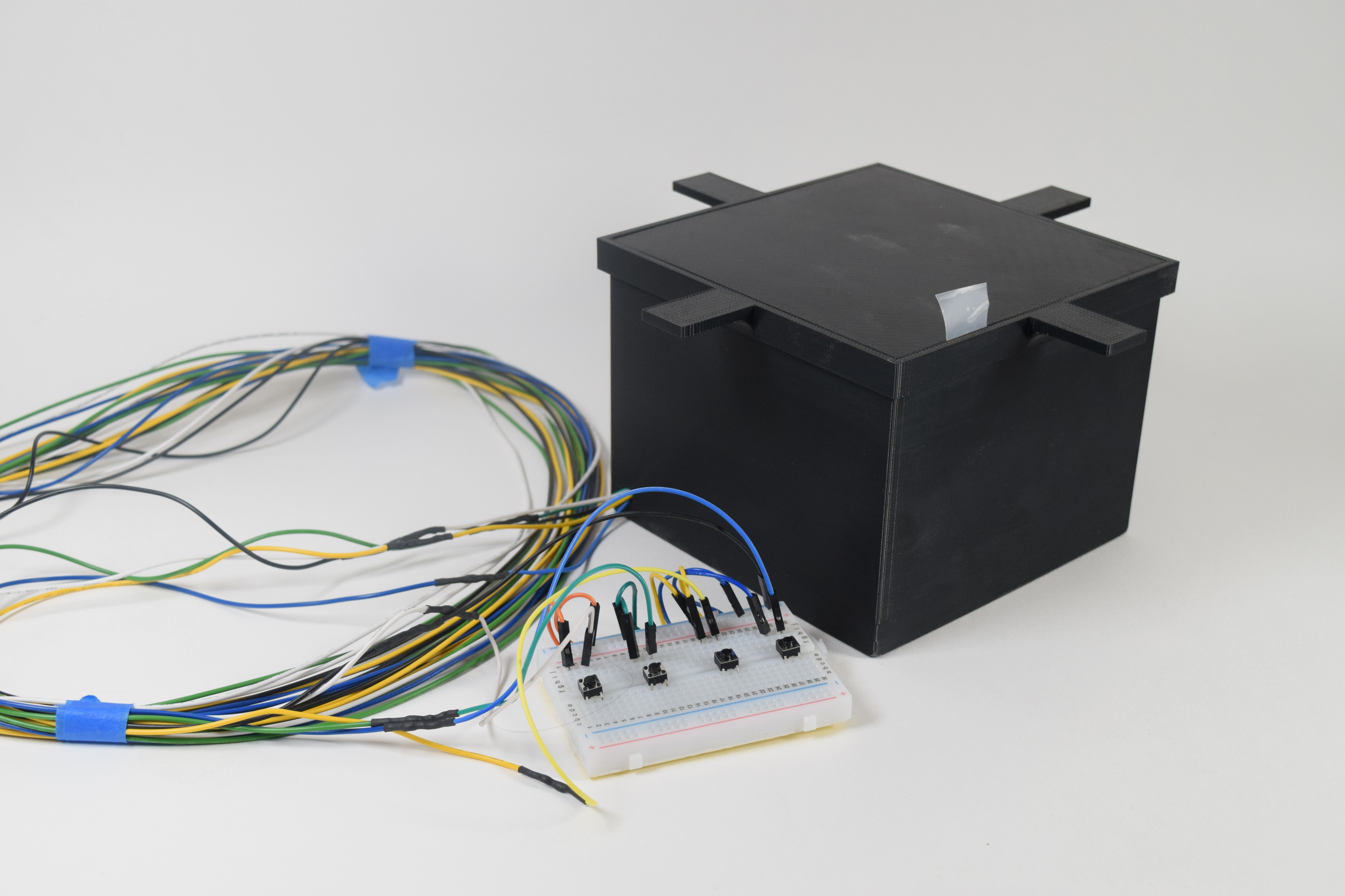
Key Reel in final presentation form with button passcode breadboard connected.
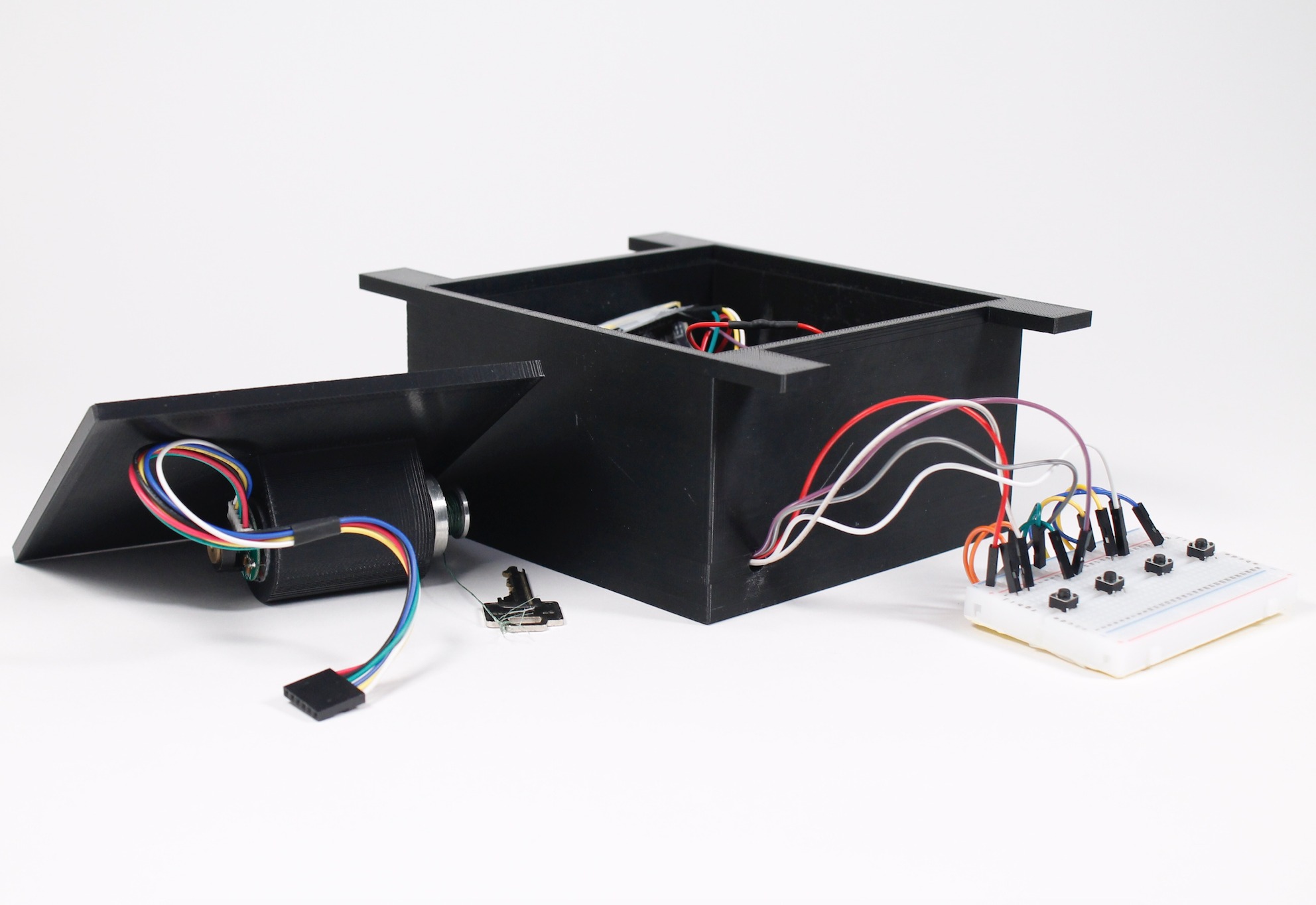
The lid has a slot to hold the motor above all the electronics inside.
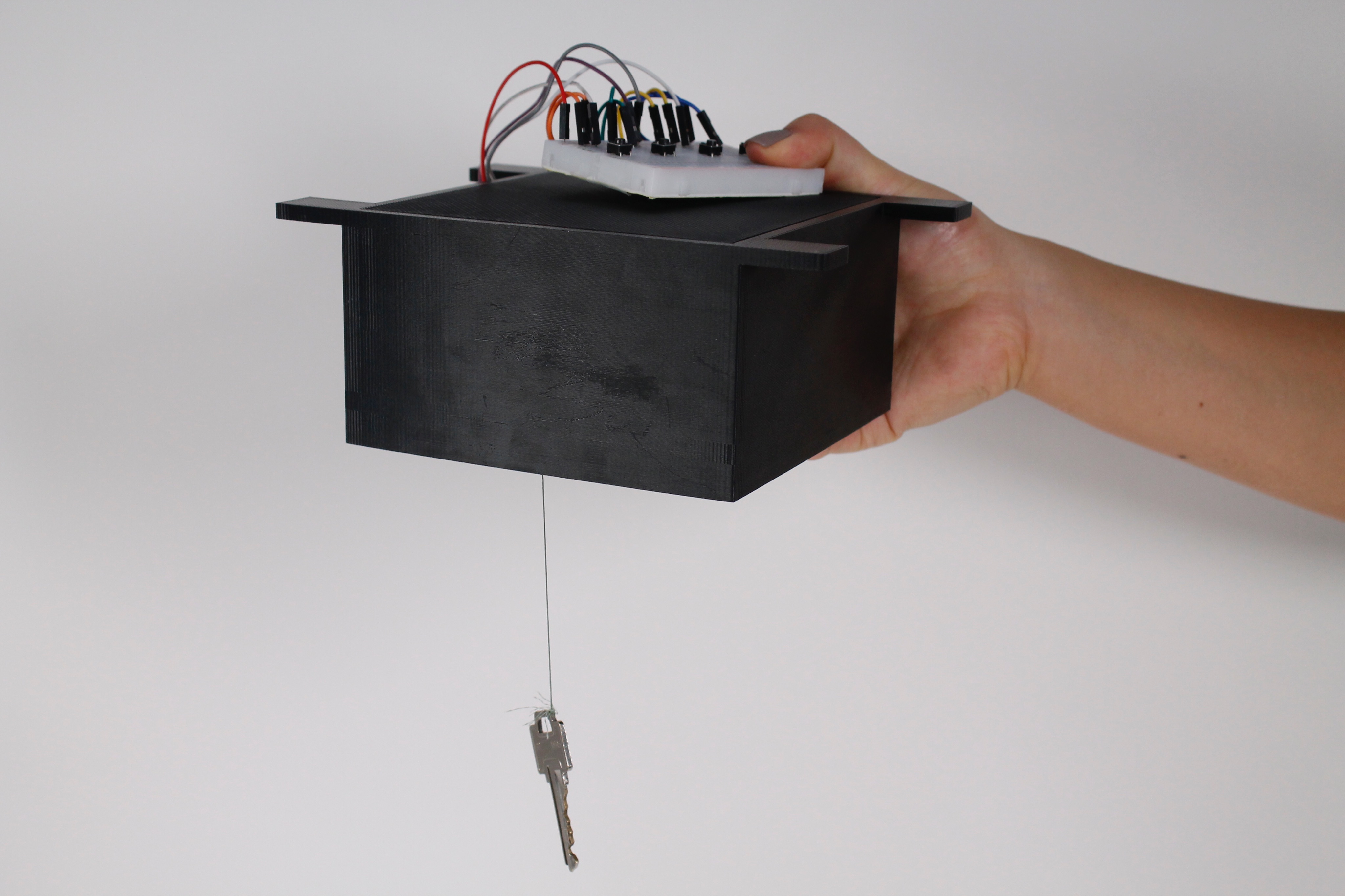
When the right passcode is pressed the motor inside the box will lower the key.
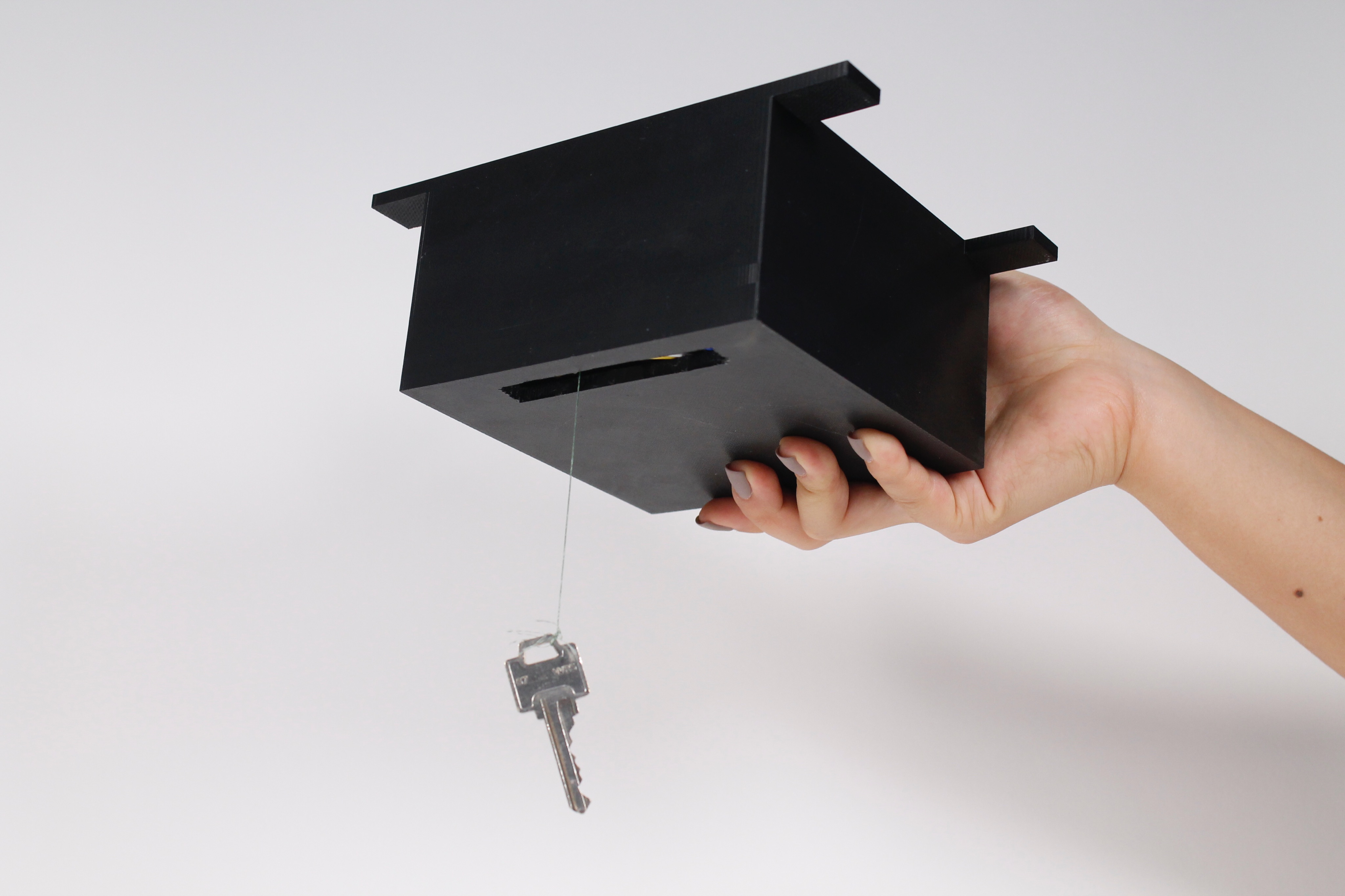
A rectangular hole in the bottom of the box allows the key to go in and out.
Quick video demonstrating the use of the Key Reel. A full video would show the full button passcode sequence as well as the key being raised all the way back into the box.
Process
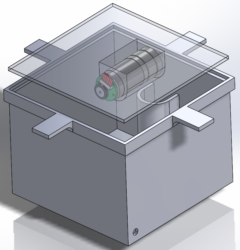
Since the electronics component of this project only deals with four push buttons and controlling a DC encoder motor I decided that the more pressing challenge would be the design and fabrication of the physical elements that would make the device look and function to how I envisioned it to. For this reason, the first thing I did was CAD and 3D print the box that would hold all the electronics shown in figure 1 and figure 2.
Figure 1: CAD Model of Box and Hardware
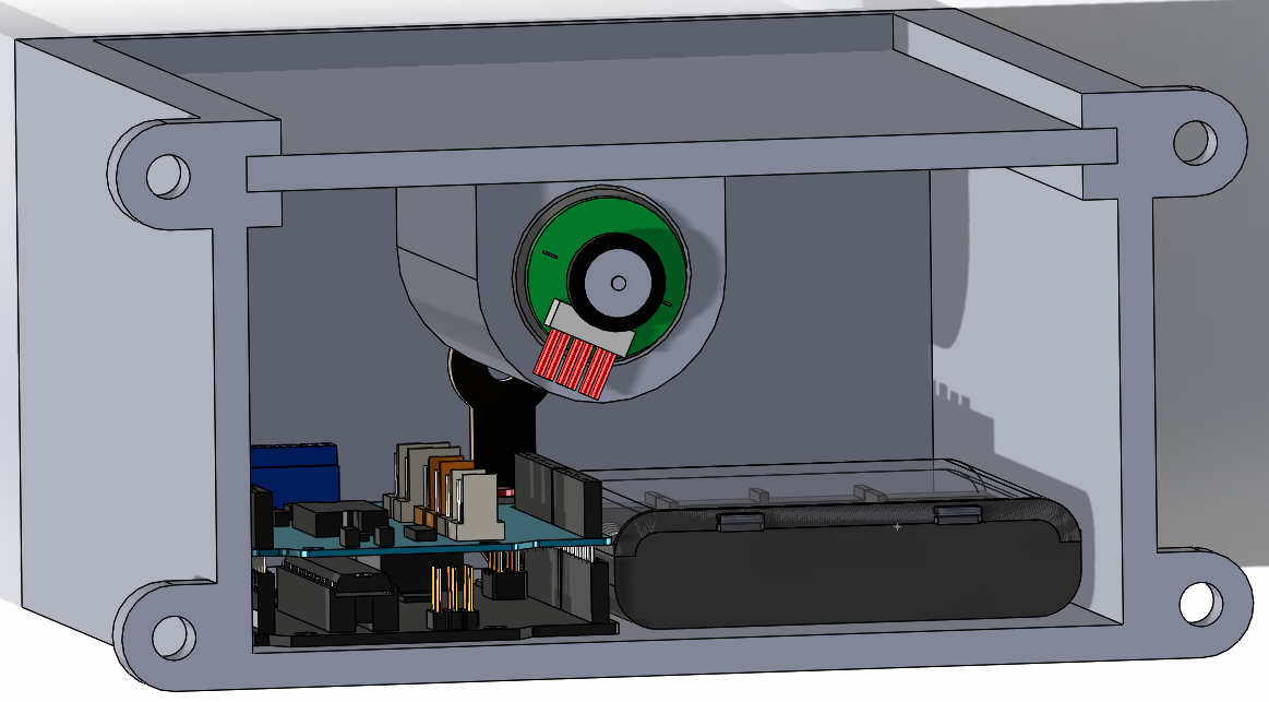
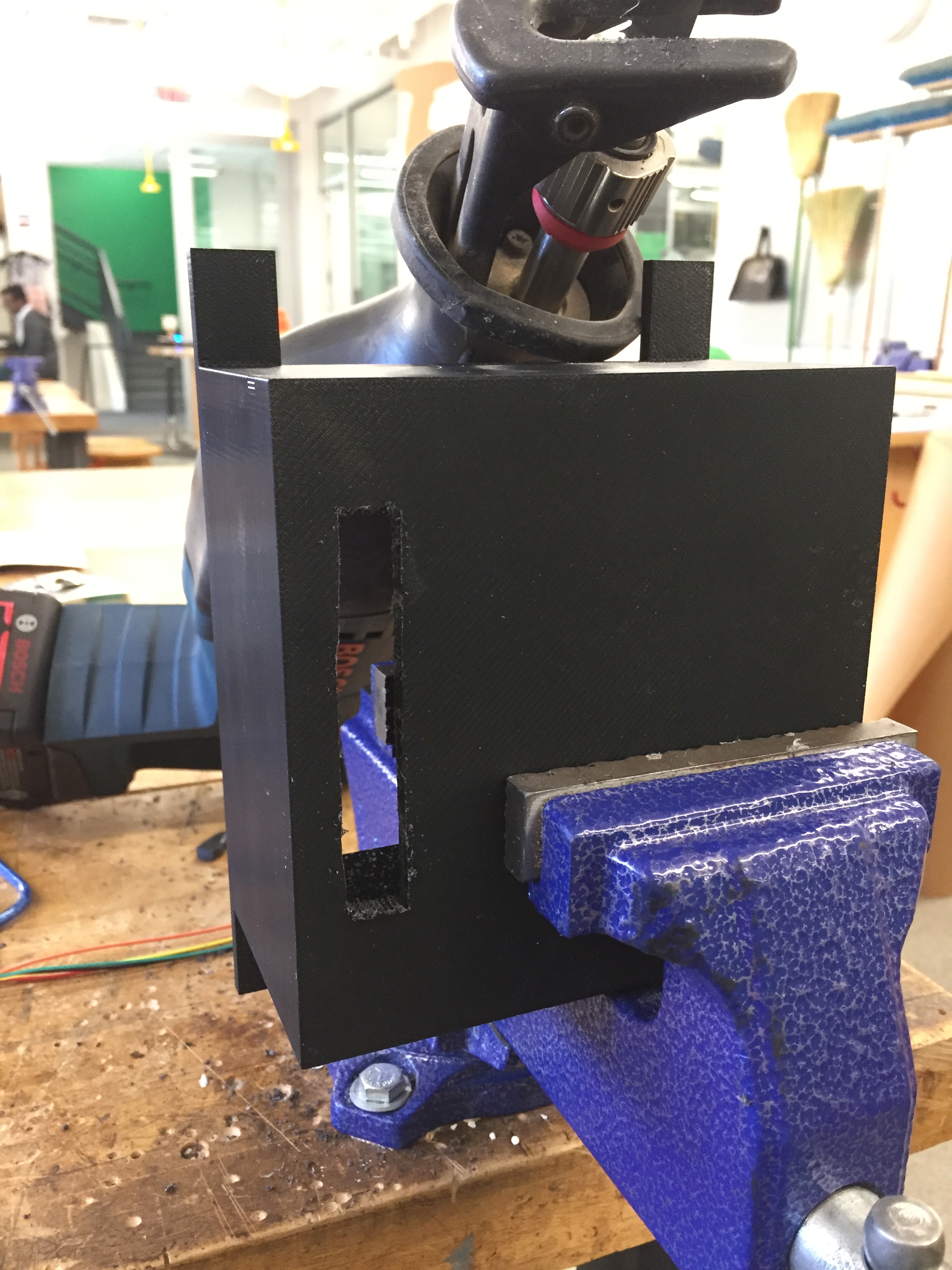
The maximum dimensions that the box could be was limited by the print space for the 3D printer I used, the Dimension Elite: (length x width x height) = (8″ x 8″ x “12”). I chose dimensions smaller than the maximum allowed because my CAD assembly showed that all the hardware would be able to fit inside a smaller volume and I wanted to limit the weight and plastic used. I eventually decided that the box should be attached to the ceiling above my door instead of the wall so I changed the CAD to make all lateral walls closed and I moved the attachment flanges to the top face. The 3D printed model in figure 2 reflects these changes.
Figure 2: 3D Printed Box
The major discrepancy between my CAD assembly and real assembly is the motor driver. When I was doing the CAD I expected to use a stackable motor shield but instead I ended up using an H-bridge because a full motor shield was unnecessary and an H-bridge is what our lab already had in stock. Using a stackable shield would have taken up less space and requires fewer wires so this ended up being a costly false assumption. The addition of a breadboard and more wires made my box more cramped than I expected so I had to make some additional effort later in my process to reduce the volume occupied by the wiring.
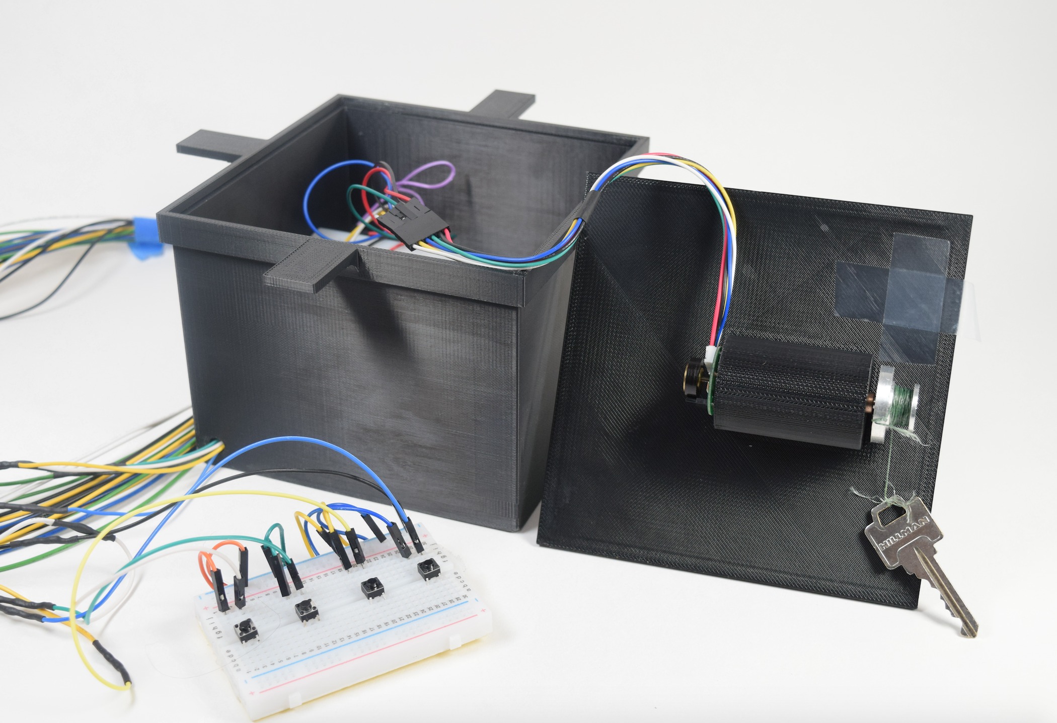
Besides holding all the hardware, the main functions of this box is to hold the motor stable as well as provide an exit and entry point for the key. The motor holder on the lid had to be aligned properly with the hole at the bottom of the box so that the motor could directly lower and raise the key. Figure 3 and figure 4 show these features.
Figure 3: Motor Holder and Key Hole
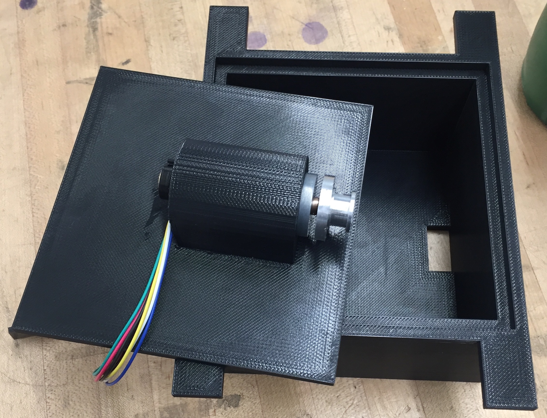
The motor holder provided a secure fit so that the motor itself didn’t rotate as it was operating. I should have spent more time on designing the entry and exit point for the key. A small rectangular hole in the bottom was not robust enough to guarantee a successful entry and exit so I had to make some on the fly adjustments later in the process. There is another hole on the box which is not shown. It is a simple quarter inch diameter hole for the wires of the passcode mechanism, which will be outside the box, to reach the Arduino.
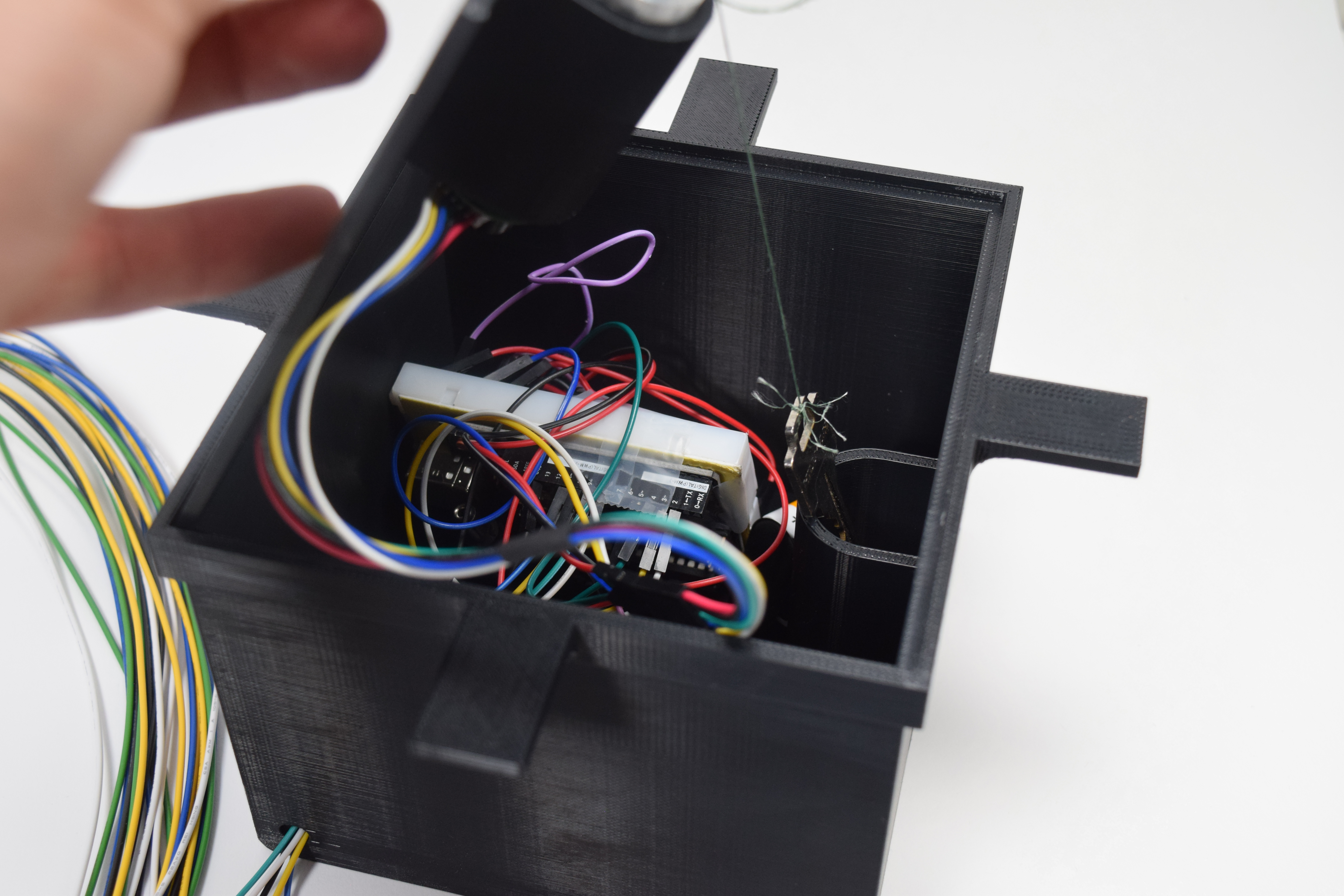
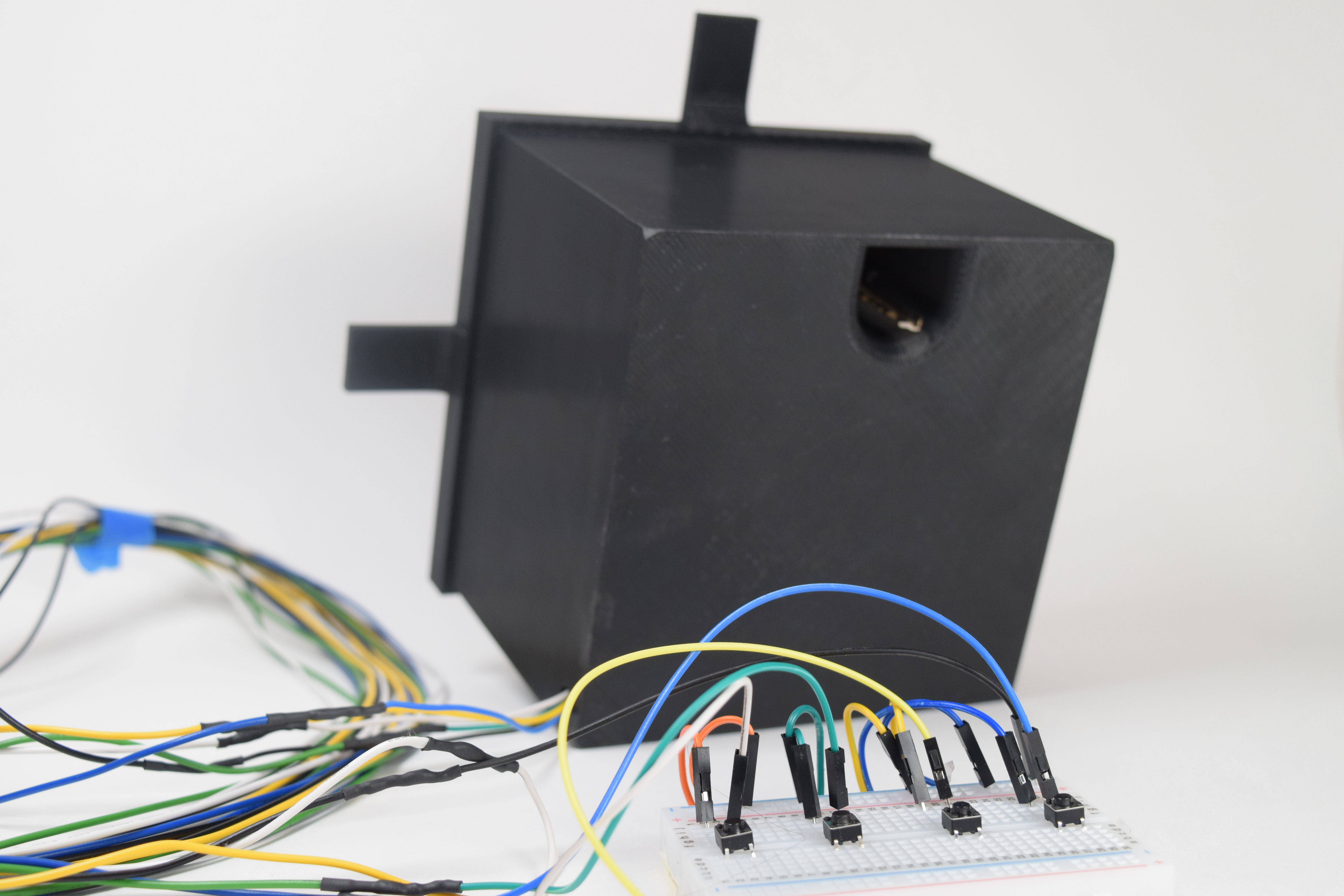
Figure 4: View of the Motor Through the Key Hole
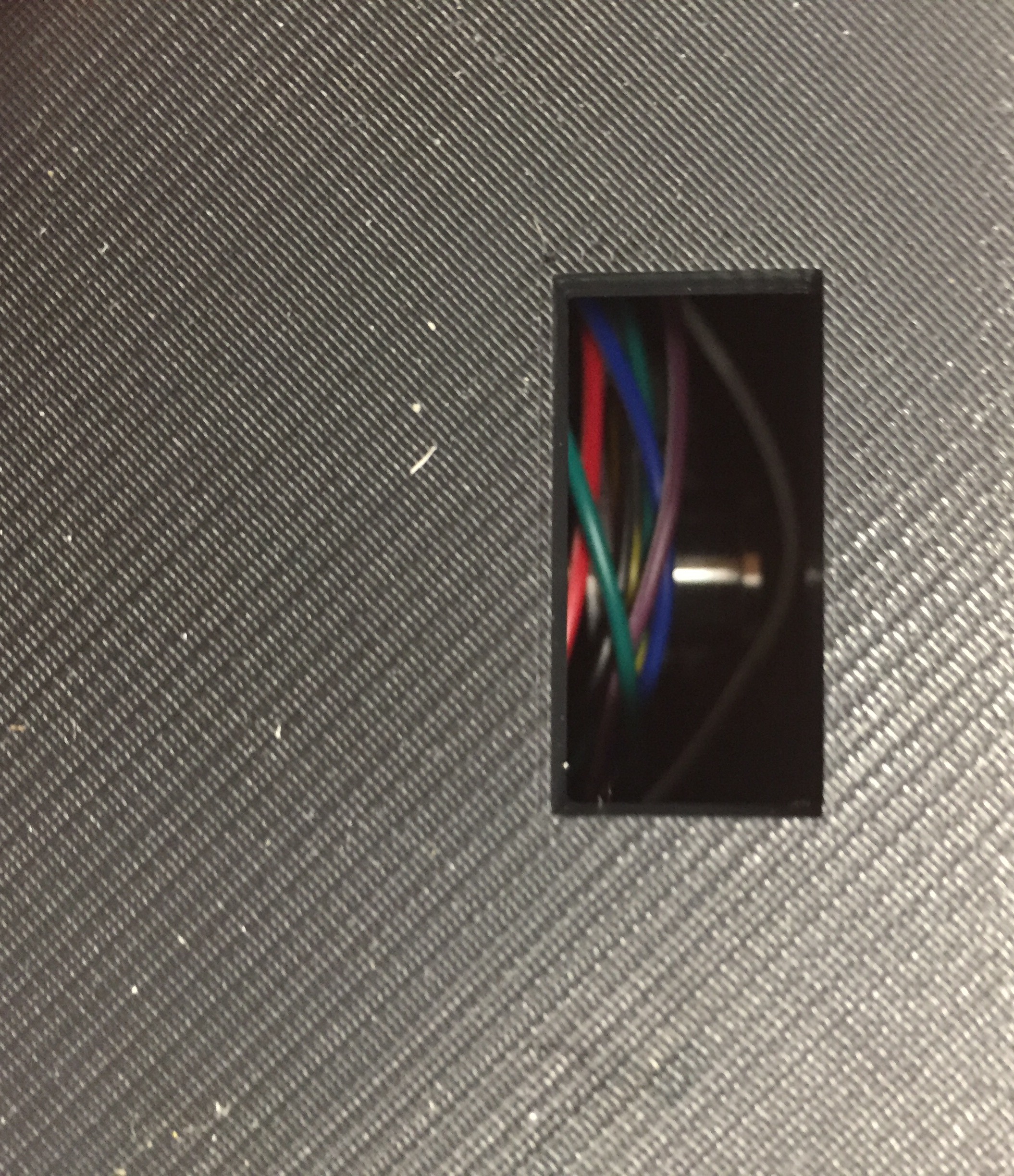
As the image shows, the pesky wires got in the way of viewing the motor shaft hub. These wires would later get in the way of raising and lowering the key so as I mentioned earlier, I would later have to constrain the wires to keep them out of the way.
As you may have already noticed, the hub on the shaft isn’t an ordinary shaft hub. This is because I had to machine it myself in order to have the functionality of performing like a fishing reel. Figures 5 through 7 illustrate the machining process as well as the final result.
Figure 5: Basic Shape Cut
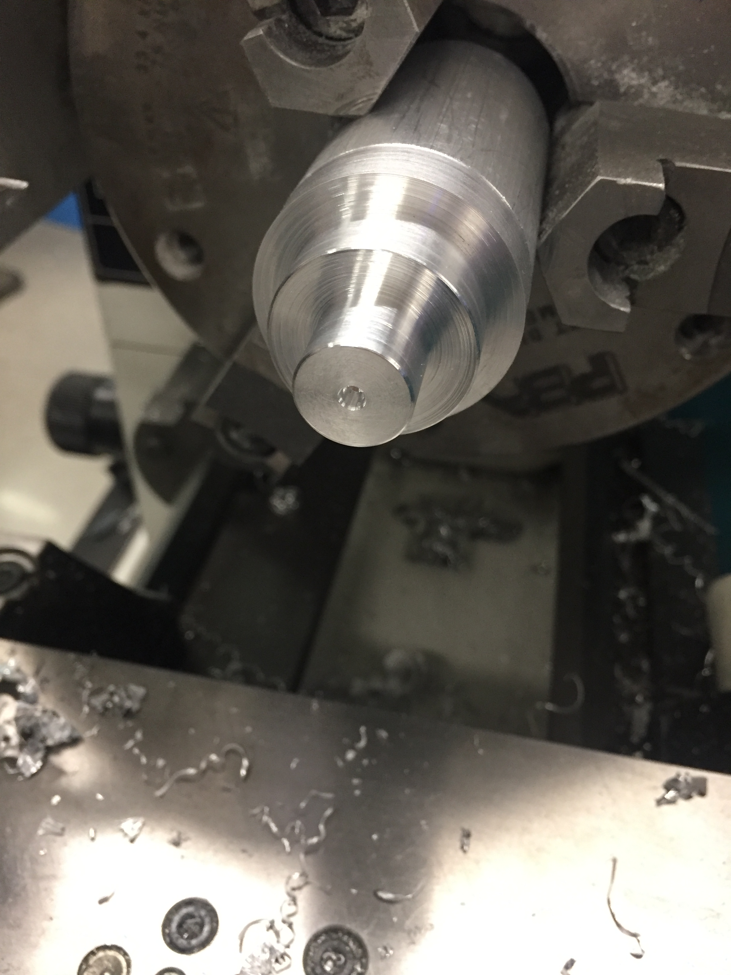
I just chose values for the diameter dimensions that seemed “about right” at the time. Had I thought more thoroughly about the intended functionality of this shaft hub I would have cut it differently but instead I just tried to make a normal looking shaft hub and then made some custom adjustments after.
Figure 6: Finished Hub
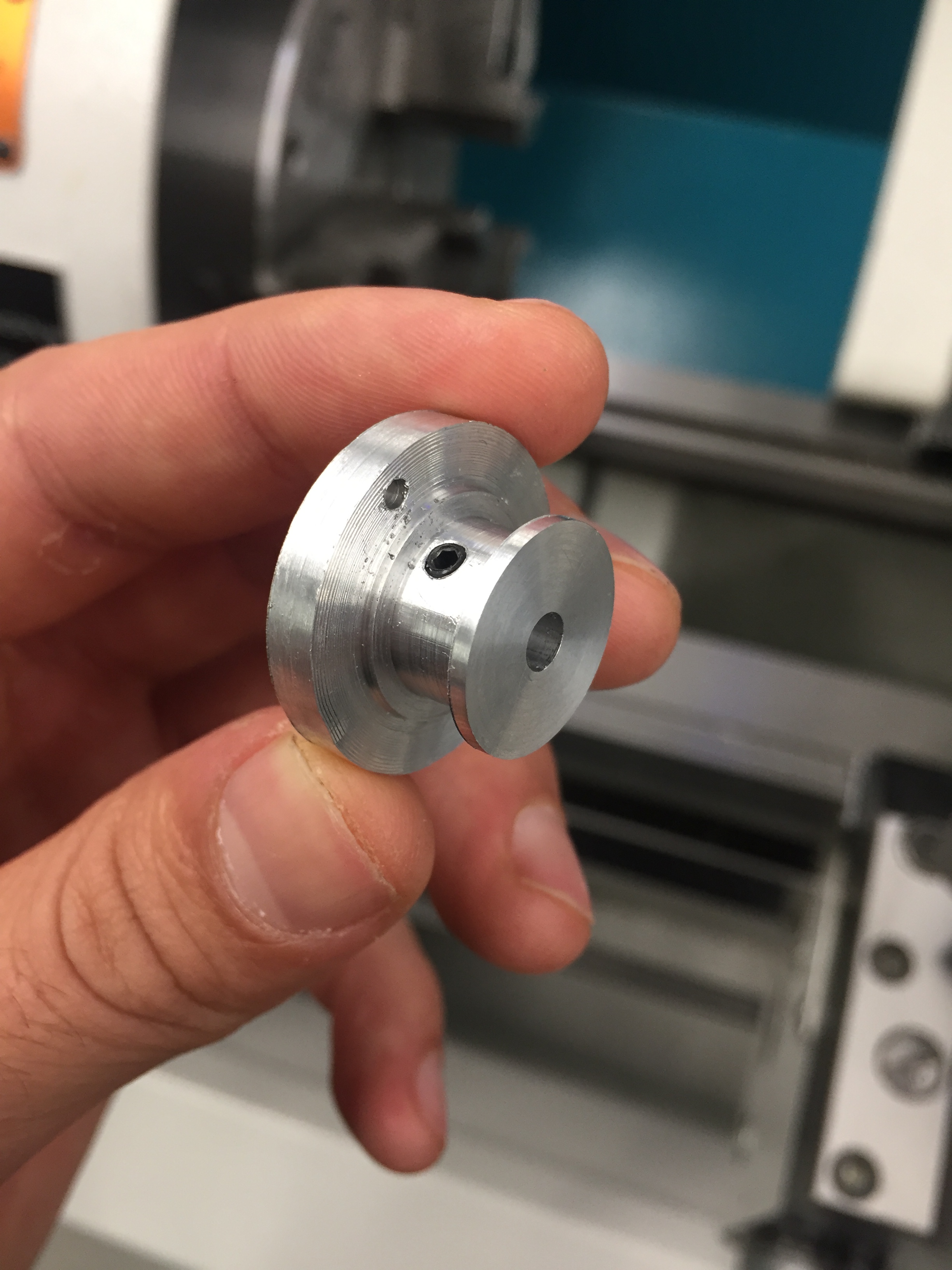
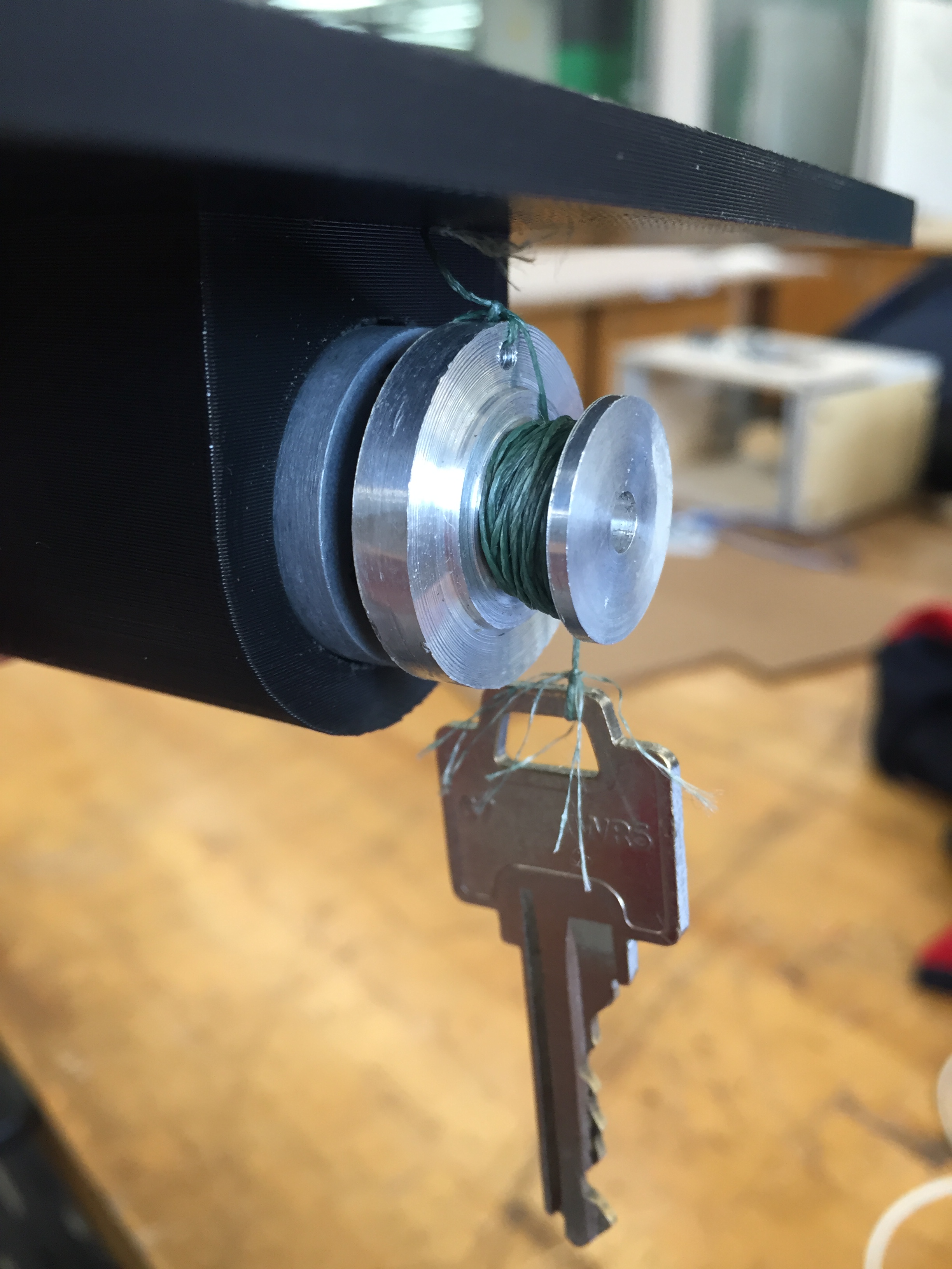
The finished hub had three through-holes in it. The concentric hole is for sliding the hub onto the motor shaft. The middle hole going radially into the center is a tapped hole for the set screw to secure the hub onto the shaft. The third hole furthest out from the center is a hole for the fishing wire to be tied to. Another custom feature of this shaft hub is that there is a wide groove in the smaller diameter portion of the hub for the wire to wrap around and not slip off the hub as it is turning. I made yet another false assumption that the fishing wire I would use would be thin enough so that the groove didn’t have to be that deep. This mistake would later present itself during the final presentation when the wire slipped off the hub as the motor was raising the key and consequently the key was not successfully reeled all the way back into the box.
Figure 7: Hub with Fishing Wire Attached
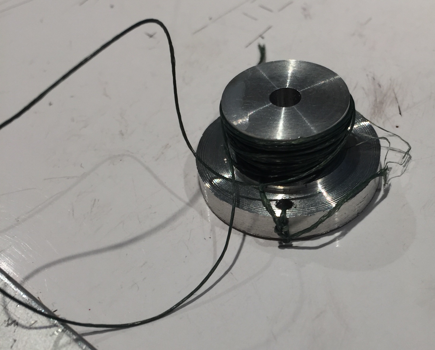
As mentioned previously, I underestimated how much wire I would need to spool around this hub. If I had more foresight, I would have kept the same outer-diameter on both ends of the hub to allow a deeper groove and ensure that the wire would not slip off.
As I predicted, getting the electronics portion of this project to function properly wasn’t too difficult. I had to learn about using an H-bridge and DC motor encoder together because this was my first time but the documentation online made the process pretty easy. Figure 8 shows the first working circuit that I put together.
Figure 8: Full Working Circuit
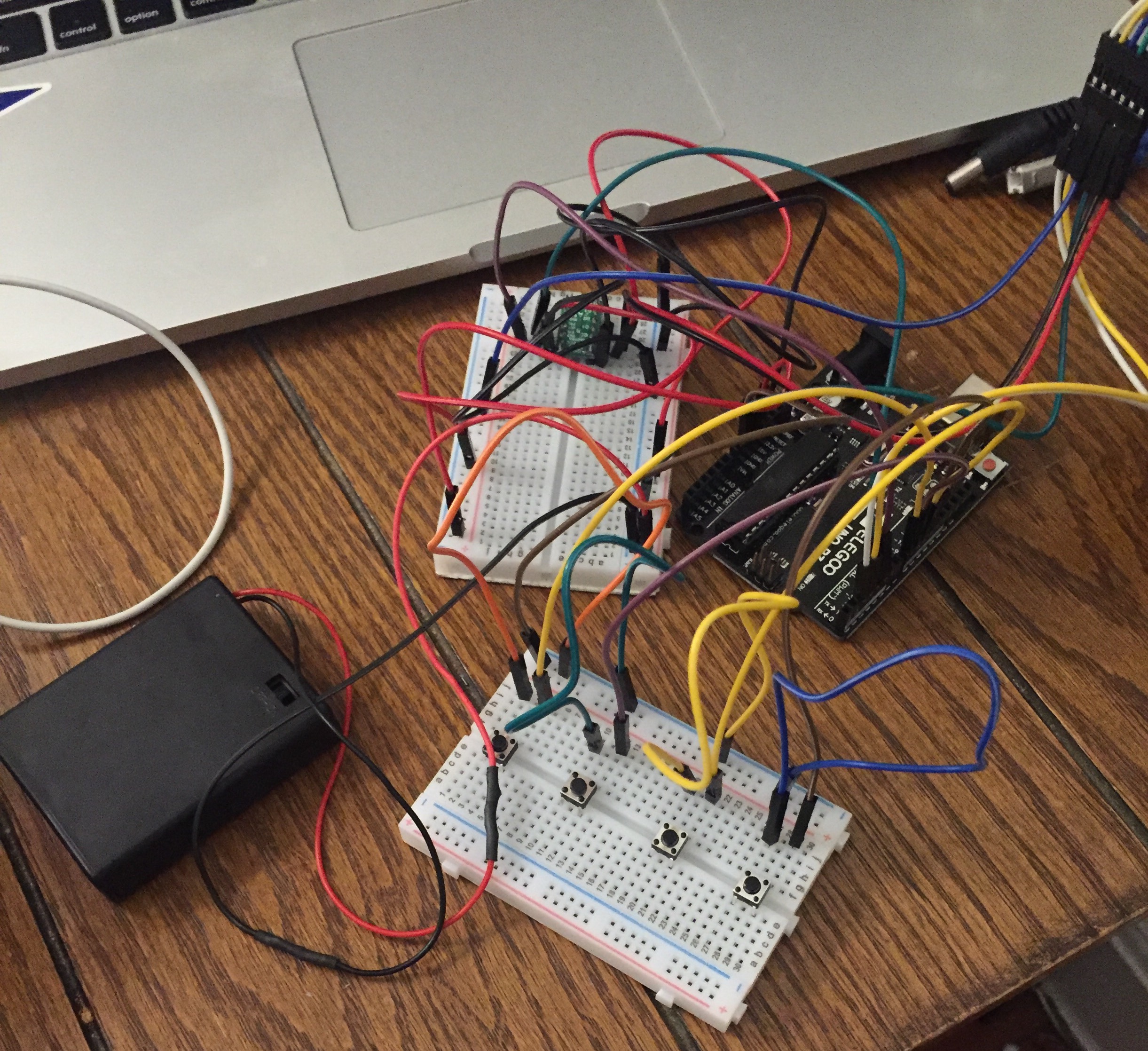
The picture cuts out the motor but the connection can be seen in the top right corner. The 9V battery that would power the Arduino is also not included but that was as simple as plugging it into the circular power jack on the Arduino. The top breadboard contains only the H-bridge that drives the motor. The bottom breadboard is reserved for the 4 push buttons that will act as the passcode device and will be the only portion besides the key itself that the user will interact with.
Since I was just trying to get everything to work I didn’t put much effort into wire management. It was only after I put everything into the box that I realized some considerable effort would be needed to contain the wires or else I would have to print a bigger box. Figures 9 through 11 show the revised circuit as well as the additional measures taken to clean up the wiring.
Figure 9: Revised Circuit
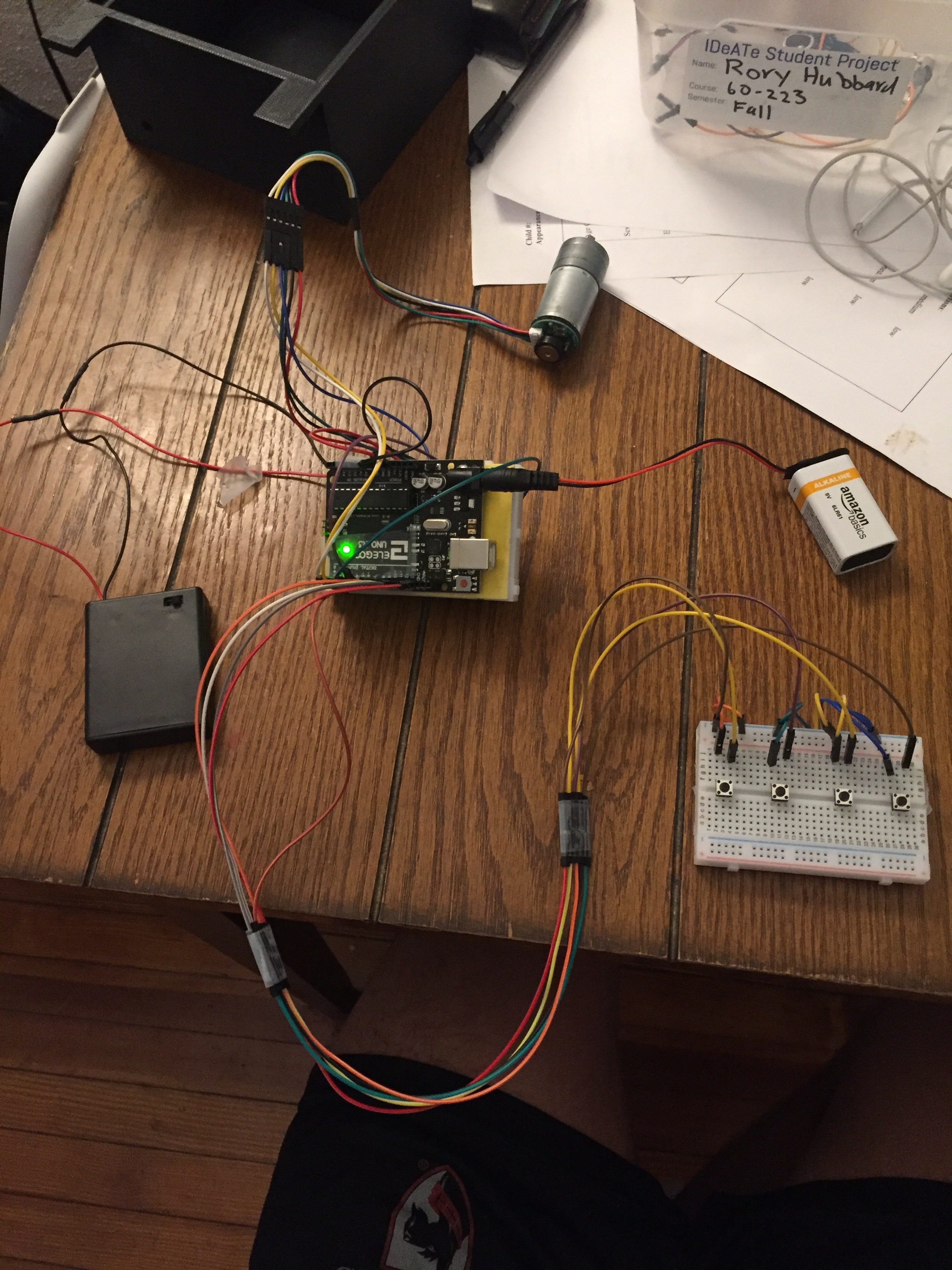
The new circuit makes the entire electronics component of the project more modular rather than one big mess of connections.
Figure 10: Arduino and H-Bridge Breadboard Taped Together
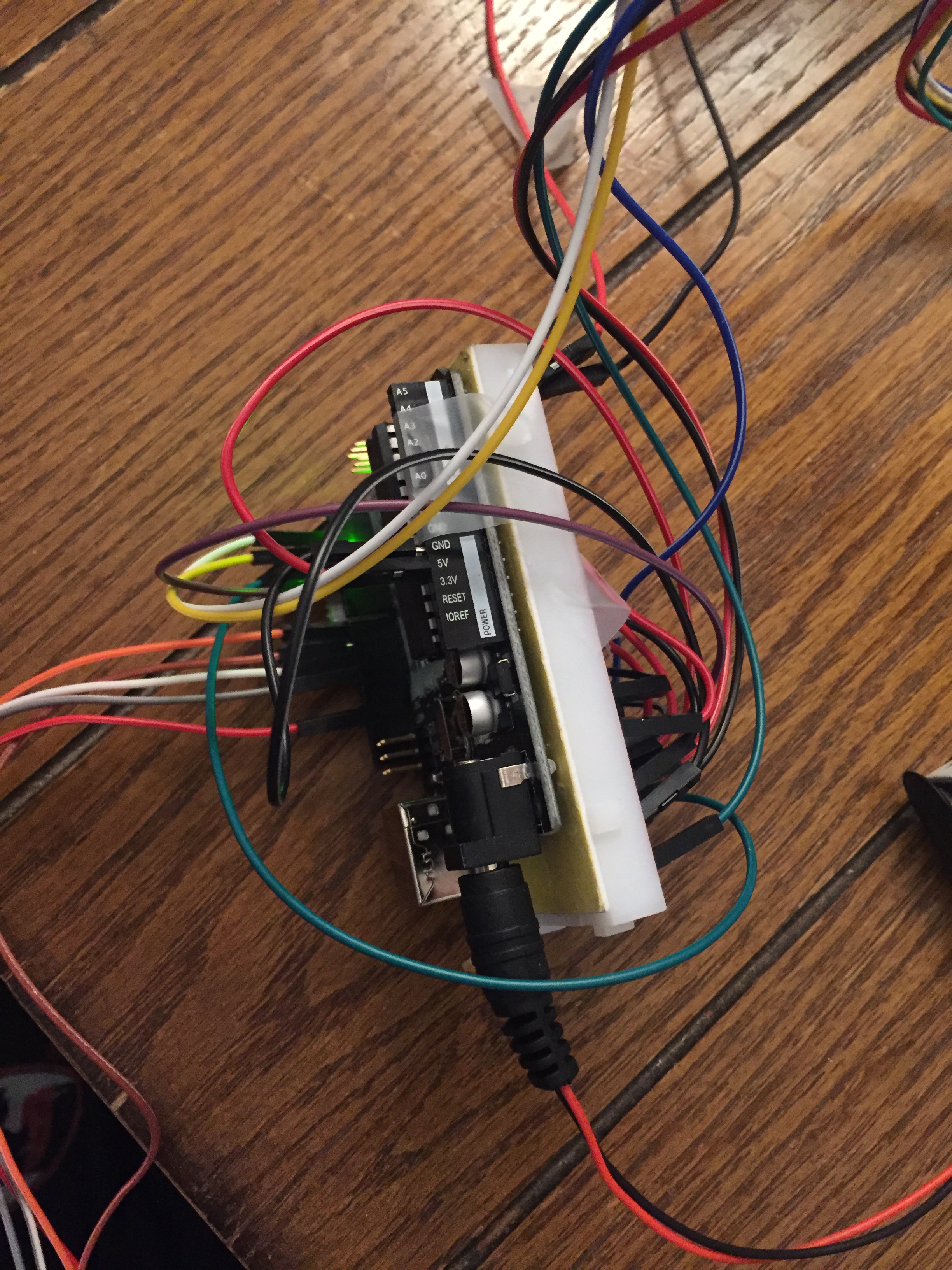
In an effort to make the H-bridge breadboard more like a stackable motor shield I taped it to the back of the Arduino.
Figure 11: Wire Containment on H-Bridge Breadboard
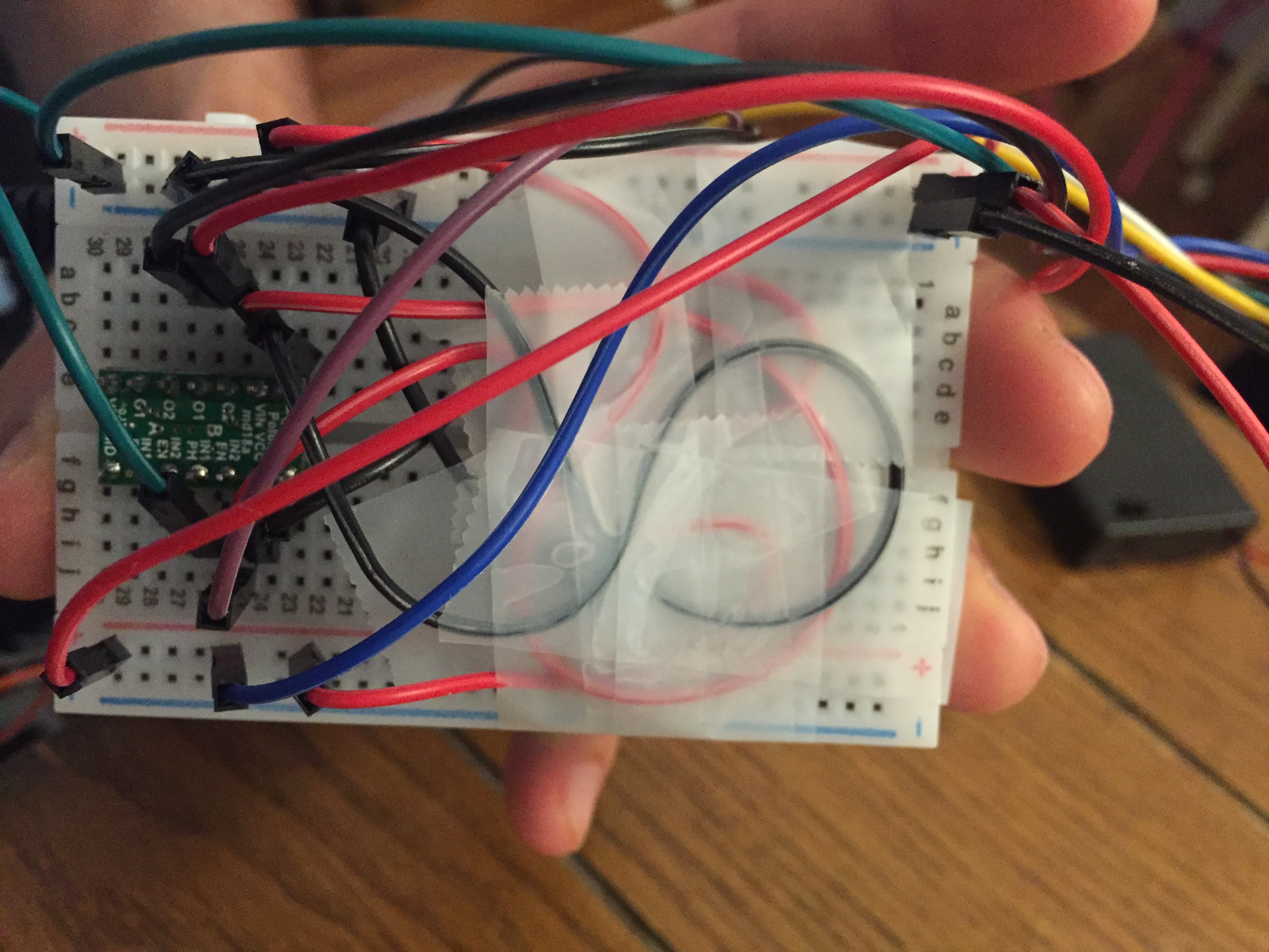
Much of the wire mess was created by the H-bridge breadboard. So to contain some of this mess I simply taped down the wires that had both ends connect to the breadboard.
With the revised circuit and the super robust wire management features in place, I was ready to put everything into the box once again. How much space had I opened up with all my rewiring and taping effort? Figure 12 will show you the answer.
Figure 12: Final Setup
Not much. Not much space at all.
After shifting the wires around and playing with the orientation of everything I managed to find a setup that worked…most of the time. The new problem that presented itself after testing was that the key hole wasn’t big enough to ensure that the key would always exit and enter successfully. So the day of the final presentation I took a reciprocating saw and made the hole bigger. Figure 13 shows this adjustment.
Figure 13: Bigger Key Hole Adjustment
For some unknown reason, I only made the key hole longer and not wider. So even after my new cut hole, the key would still sometimes get caught on its way back into the box. By this time it was too late for me to go back and cut it again, it was time to present!
Discussion
One student suggested that I could have implemented “another mechanism that closes the bottom of the box when the key is inside.” I definitely toyed around with this idea in my head for a while but after some consideration I thought it would make things too complicated. I still wanted the key to be somewhat hidden though once it was inside the box and that was why my box design only had a small rectangular hole in the bottom that was barely big enough for the key to fit through. This design decision was a consequence of me thinking more about how I wanted the device to appear than how I wanted the device to function. This revealed my failure to really consider how the key would be moving as it exited and entered the box. More than likely the key would be swinging a little especially on its way back into the box and if I had thought about this then it would have been pretty easy to implement some sort of funnel feature that helped guide the key in and out of the box. Out of all the mistakes and false assumptions I made during this project, the faulty key hole is the blunder that I am most disappointed about. I usually am good at thinking about how something will move or function ahead of time and making design decisions in order to achieve proper performance even in “worst-case scenario” situations. For this device, the “worst-case scenario” is that the key is oriented in such a way that it doesn’t fit through the hole at the box boundary. This poor design decision upset me the most because my other mistakes were a product of a false prediction like assuming I would use a motor shield or thinking that the fishing wire would be adequately thin enough. While these false predictions could have been avoided, they don’t bother me as much because I was just trying to get things done quickly rather than wait until I had all the gear before I started designing and fabricating. I designed the key hole knowing exactly what the dimensions were on the key so I had all the information that I needed. It was just a lazy design for a crucial feature of my project. To make things worse, even after I adjusted the hole with a saw it still didn’t guarantee proper performance because I only made it bigger in one direction. I think throughout the entire project I was lackadaisical about applying a real engineering thought process and this was evident by how many mistakes I made along the way. I underestimated how many things could go wrong when trying to make a simple box that lowered and raised a key. Going through the process of developing this project showed me that doing a little thinking ahead of time instead of rushing into making something and getting things done will actually save time in the long run. I spent almost more time correcting my previous mistakes and faulty designs than I did in designing, fabricating, and writing code. I learned some new technical skills from this project like how to use an H-bridge and DC motor encoder but the main lesson that will stay with me is that I must utilize an engineering framework when developing even the simplest of projects.
Another student wrote that “the button part could be designed better, it looks a little rough now.” I agree that it looks a little scrappy using four push buttons on a breadboard as the passcode but this is a look that I actually like. A common observer will view the breadboard and be kind of curious as to what it does while a passcode immediately tells a person that there is something that only a person who knows the passcode should be able to do or achieve. In this case it would be having access to the house key. I am not too concerned with security at my house. We leave the main door unlocked all the time anyways. This device is for the side door that my floor mates and I use. So rather than making my key reel secure and private, I want it to be more friendly and interactive. I want to entice visitors to use the button board and try to figure out what it is used for. I will keep a simple passcode for now to get my floor mates to start to use this device but eventually I want to change the code to something more interesting like 31415 in 4 bit binary. Then I would leave a sign that gives a clue to what the code is. Whoever strolls to the side of my house and happens to know pi in 4 bit binary is welcome to come in all days of the week as far as I’m concerned.
Further Development
After the final presentation I felt that with just a few adjustments and I could correct all my mistakes and make the device reliable enough to actually use. So first, I redesigned the box. Figure 14 and 15 show the redesign in CAD.
Figure 14: Box Redesign
The key now has its own chamber within the box so that it is no longer at risk of being disturbed by wires or any other hardware within the box. Some other revisions include thinning the walls to reduce unnecessary use of plastic as well as weight. The overall dimensions were increased to allow for more space for all the hardware. And the flanges that will be used to attach the box to the ceiling are now located in the middle of each edge to evenly distribute the holding points.
Figure 15: Key Funnel
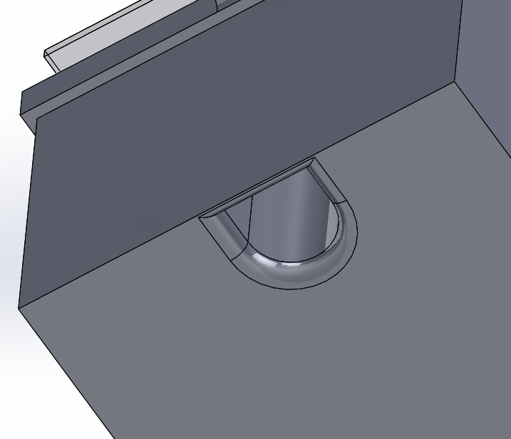
Another major improvement of this design is that the key entry and exit point isn’t just a rectangular hole anymore. It is a more appropriate rounded cross section with fillets around the edge to funnel the key back into the box.
Figure 16 through 19 show images of the final 3D printed Key Reel Device.
Figure 16: Final Setup
This image contains everything that will allow this device to be installed above my house door and to perform to how I envisioned. The long wires going from the button board to the box will allow the user to easily interact with the device while the box is taped to the ceiling way out of arms reach. The piece of tape sticking out of the top of the box is for easy removal of the lid.
Figure 17: Box with Lid Off
With the larger dimensions on the box, all the electronics resting inside are nearly out of sight from this viewpoint.
Figure 18: Internal Key Chamber
The internal key chamber separates the key’s movement path from all the electronics and significantly increases the reliability of the device’s actuation.
Figure 19: Key Funnel
The key funnel ensures a successful re-entry of the key regardless of the key’s orientation.
Next I took the shaft hub back to the lathe to make the groove for the wire to spool around a little deeper. Figure 20 shows the revised shaft hub.
Figure 20: Revised Shaft Hub
Now the wire is much less likely to fall off the hub while the motor is turning.
I’ve tested the new and improved Key Reel many times now and it has performed with a 100% success rate. I’m excited to install the box above my door and start using it!
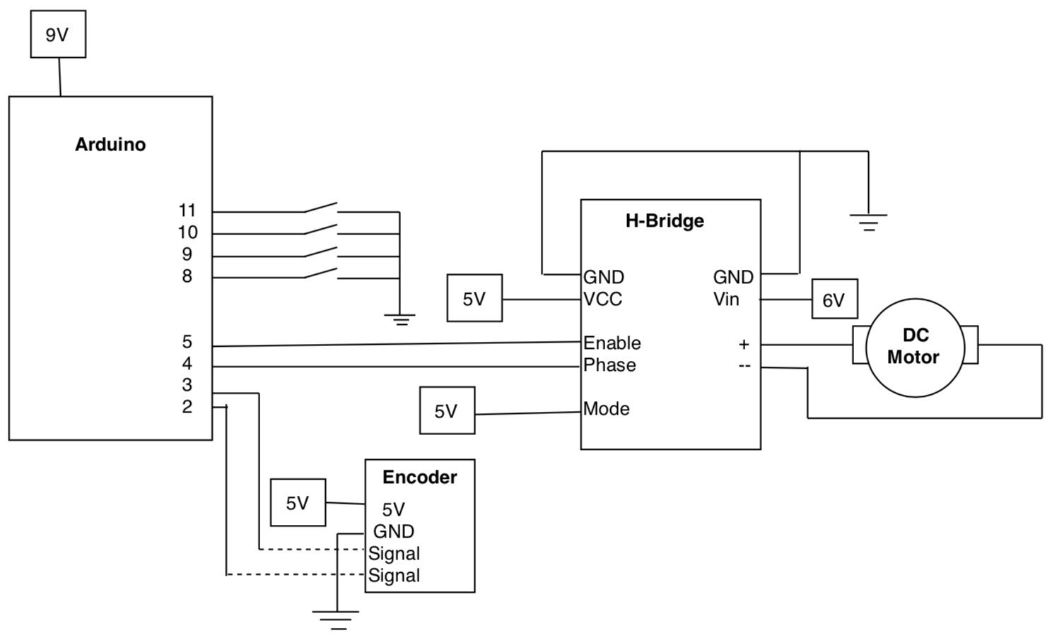
Schematic
Code
/*
 * Project 2 - Key Dispenser
 * Rory Hubbard - chubbard
 * 10/25/18
 *
 * This code takes readings from four push buttons and a rotary encoder to
 * operate a DC motor. The buttons must be pressed in a specific sequence
 * to turn on the motor. Once the motor is turned on and has moved a specified
 * distance that is calculated by the encoder, the motor brakes to a halt. Then at the
 * press of another button the motor turns the other way to go back to its original
 * starting location. The code to read the encoder is borrowed from a library that Paul Stoffrogen wrote.
 *
 */

// include encoder library
#include <Encoder.h>

// define pins
// PHASE pin connects to the H-bridge and tells the motor which way to turn
const int PHASE = 4;
// PWM pin connects to the H-bridge and tells the motor the speed to rotate at
const int PWM = 5;
// ENCODER pins read the outputs from the encoder to detect the angular position of the motor
const int ENCODERWHITE = 2;
const int ENCODERYELLOW = 3;
// BUTTON pins read whether the corresponding button is pressed or not
const int BUTTON1PIN = 8;
const int BUTTON2PIN = 9;
const int BUTTON3PIN = 10;
const int BUTTON4PIN = 11;

// establish encoder pins for encoder library
Encoder myEnc(ENCODERWHITE, ENCODERYELLOW);

void setup() {
  Serial.begin(9600);
  pinMode(PHASE,OUTPUT);
  pinMode(PWM,OUTPUT);
  pinMode(BUTTON1PIN,INPUT_PULLUP);
  pinMode(BUTTON2PIN,INPUT_PULLUP);
  pinMode(BUTTON3PIN,INPUT_PULLUP);
  pinMode(BUTTON4PIN,INPUT_PULLUP);
}

// establish variables for encoder reading
long oldPosition  = -999;
long newPosition;
// the desired position for the encoder value corresponds to the number of revolutions for the key to be sufficiently lowered
long desiredPosition = 10000;

// establish variables for motor control
int motorDirection = 0;
int motorSpeed = 0;
// the set speed is on a scale of 0-255
int speedSet = 200;

// the "keyMoving" variable keeps track of whether the key is being raised or lowered at the present moment
bool keyMoving = false;

// the human interaction with this key reel is sequential in nature so the code is written in a way to reflect that
// the "sequence" variable keeps track of which sequential step the user is currently on
int sequence = 0;

void loop() {

  // read encoder
  newPosition = myEnc.read();
  if (newPosition != oldPosition) {
    oldPosition = newPosition;
    //Serial.println(newPosition);
  }

  // read button states
  int button1 = digitalRead(BUTTON1PIN);
  int button2 = digitalRead(BUTTON2PIN);
  int button3 = digitalRead(BUTTON3PIN);
  int button4 = digitalRead(BUTTON4PIN);

  // sequence numbers 1 - 4 are for the passcode entry
  // the buttons will only affect the sequence when the key is at a halt
  // the passcode is the buttons pressed in numerical order

  if (button1 == LOW && sequence < 4 && keyMoving == false) {
    motorDirection = 1; // motor direction of 1 corresponds to the way the motor needs to turn to lower the key
    sequence = 1; // button 1 is the first button in the sequence so the sequence variable goes to 1 now
    //Serial.println(sequence);
  }

  // if button 1 was previously pressed and the key isn't currently in transit, button 2 is next in the passcode sequence
  if (button2 == LOW && sequence == 1 && keyMoving == false) {
    sequence = 2;
    //Serial.println(sequence);
  }

  // button 2 will reset the sequence if the sequence variable is not equal to 1 or 2
  // writing the code this way allows for the buttons to be pressed multiple times or held down as long as they are pressed in order
  else if (button2 == LOW && (sequence < 1 || sequence > 2) && keyMoving == false) {
    sequence = 0;
    //Serial.println(sequence);
  }

  // if button 2 was previously pressed and the key isn't currently in transit, button 3 is next in the passcode sequence
  if (button3 == LOW && sequence == 2 && keyMoving == false) {
    sequence = 3;
    //Serial.println(sequence);
  }

  // button 3 will reset the sequence if the sequence variable is not equal to 2 or 3
  else if (button3 == LOW && (sequence < 2 || sequence > 3) && keyMoving == false) {
    sequence = 0;
    //Serial.println(sequence);
  }

  // if button 3 was previously pressed and the key isn't currently in transit, button 4 is next in the passcode sequence
  if (button4 == LOW && sequence == 3 && keyMoving == false) {
    sequence = 4;
    //Serial.println(sequence);
  }

  // button 4 will reset the sequence if the sequence variable is not equal to 3 or 4
  else if (button4 == LOW && (sequence < 3 || sequence > 4) && keyMoving == false) {
    sequence = 0;
    //Serial.println(sequence);
  }

  // if the sequence variable reaches 4 then the right passcode has been entered and the key should be lowered down
  if (sequence == 4 && keyMoving == false) {
    sequence = 5;
    motorSpeed = speedSet;
    keyMoving = true;
    digitalWrite(PHASE,motorDirection);
    analogWrite(PWM,motorSpeed);
    //Serial.println(sequence);
  }

  // brake the motor when the encoder reads that the motor is at or exceeded the desired position
  // this means the key has been lowered to a sufficient depth
  if (newPosition >= desiredPosition && sequence == 5) {
    sequence = 6;
    motorSpeed = 0;
    keyMoving = false;
    digitalWrite(PHASE,motorDirection);
    analogWrite(PWM,motorSpeed);
    //Serial.println(sequence);
  }

  // when the user is ready to raise the key back into the box then they just need to press button 1 again
  if (button1 == LOW && sequence == 6 && keyMoving == false) {
    sequence = 7;
    motorDirection = 0; // motor direction of 2 corresponds to the way the motor needs to turn to raise the key
    motorSpeed = speedSet;
    keyMoving = true;
    digitalWrite(PHASE,motorDirection);
    analogWrite(PWM,motorSpeed);
    //Serial.println(sequence);
  }

  // brake the motor when the encoder reads that the motor is back to its starting location
  // this means the key has been raised back into the box
  if (newPosition <= 0 && sequence == 7 && keyMoving == true) {
    sequence = 0; // the full sequence has been complete so reset the sequence variable back to 0
    motorSpeed = 0;
    keyMoving = false;
    digitalWrite(PHASE,motorDirection);
    analogWrite(PWM,motorSpeed);
    //Serial.println(sequence);
  }

}
Leave a Reply
You must be logged in to post a comment.