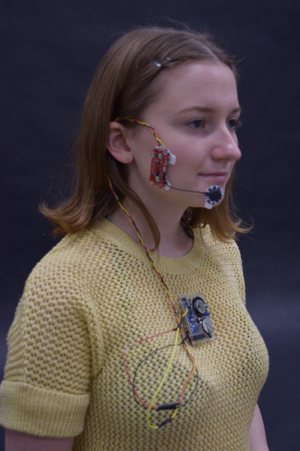
A warning device to measure when jaw tension enters the stress headache territory.

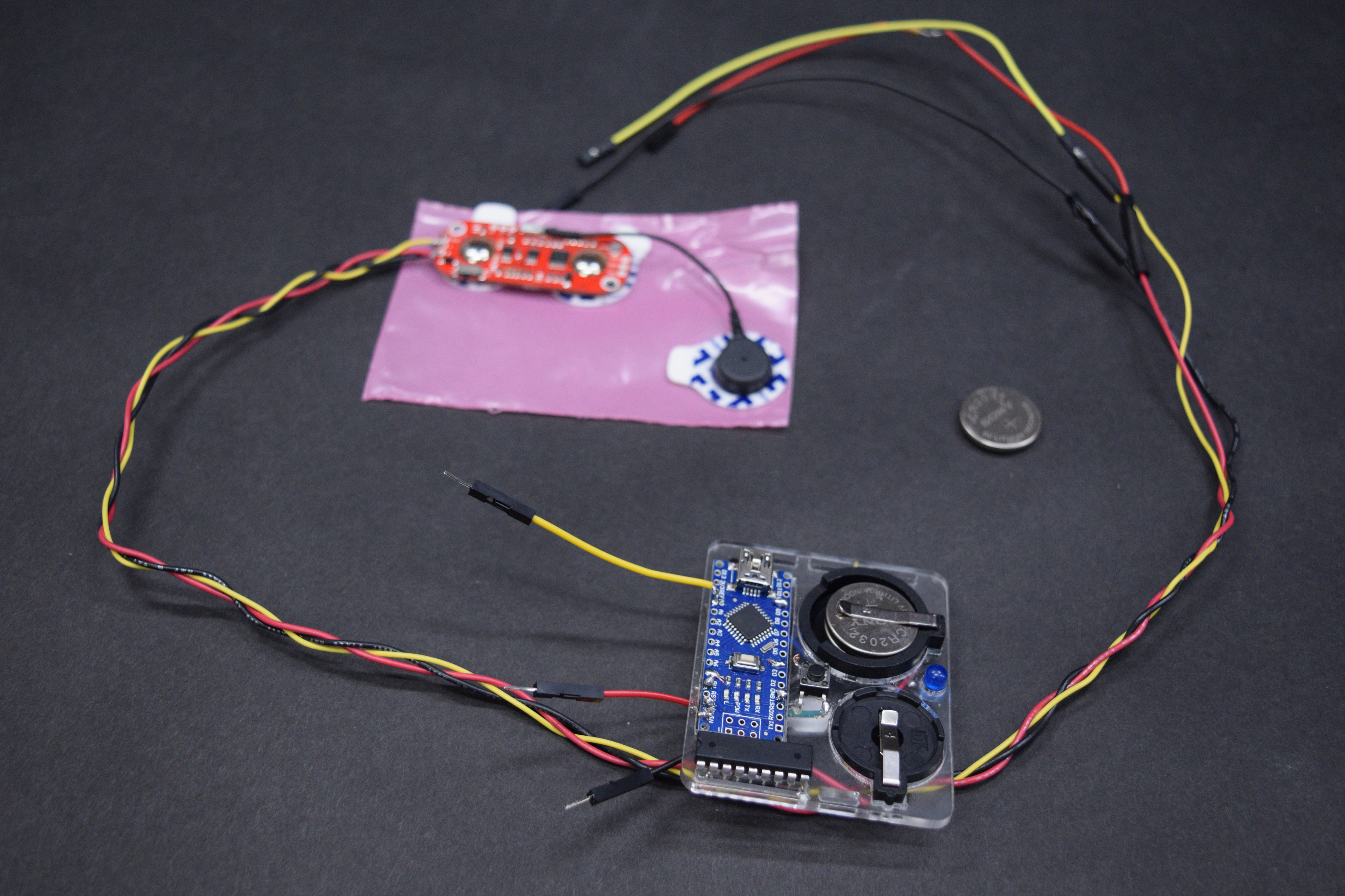
The full set: The muscle sensor with detachable wires connects to the body piece to send information to the Arduino Mini.
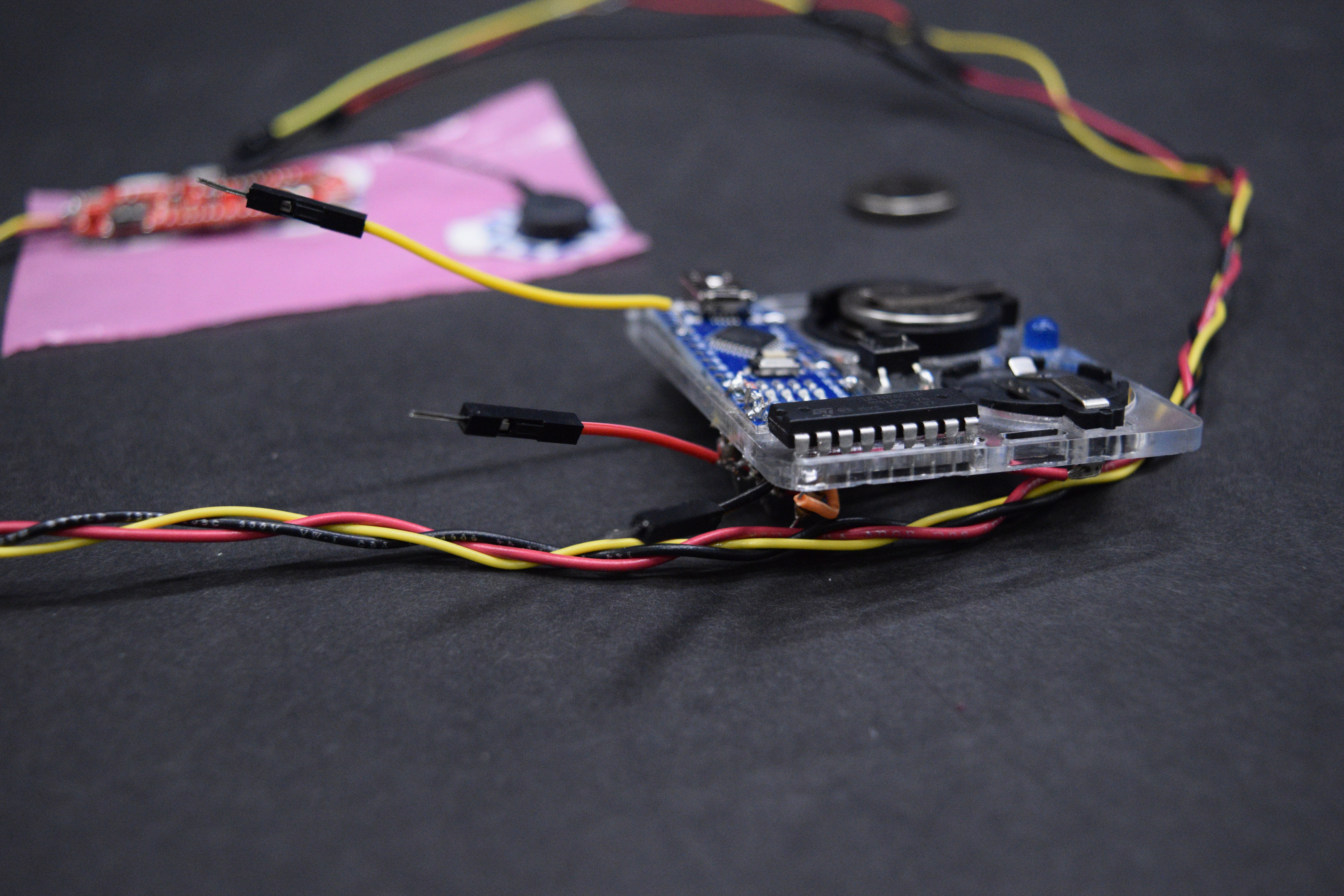
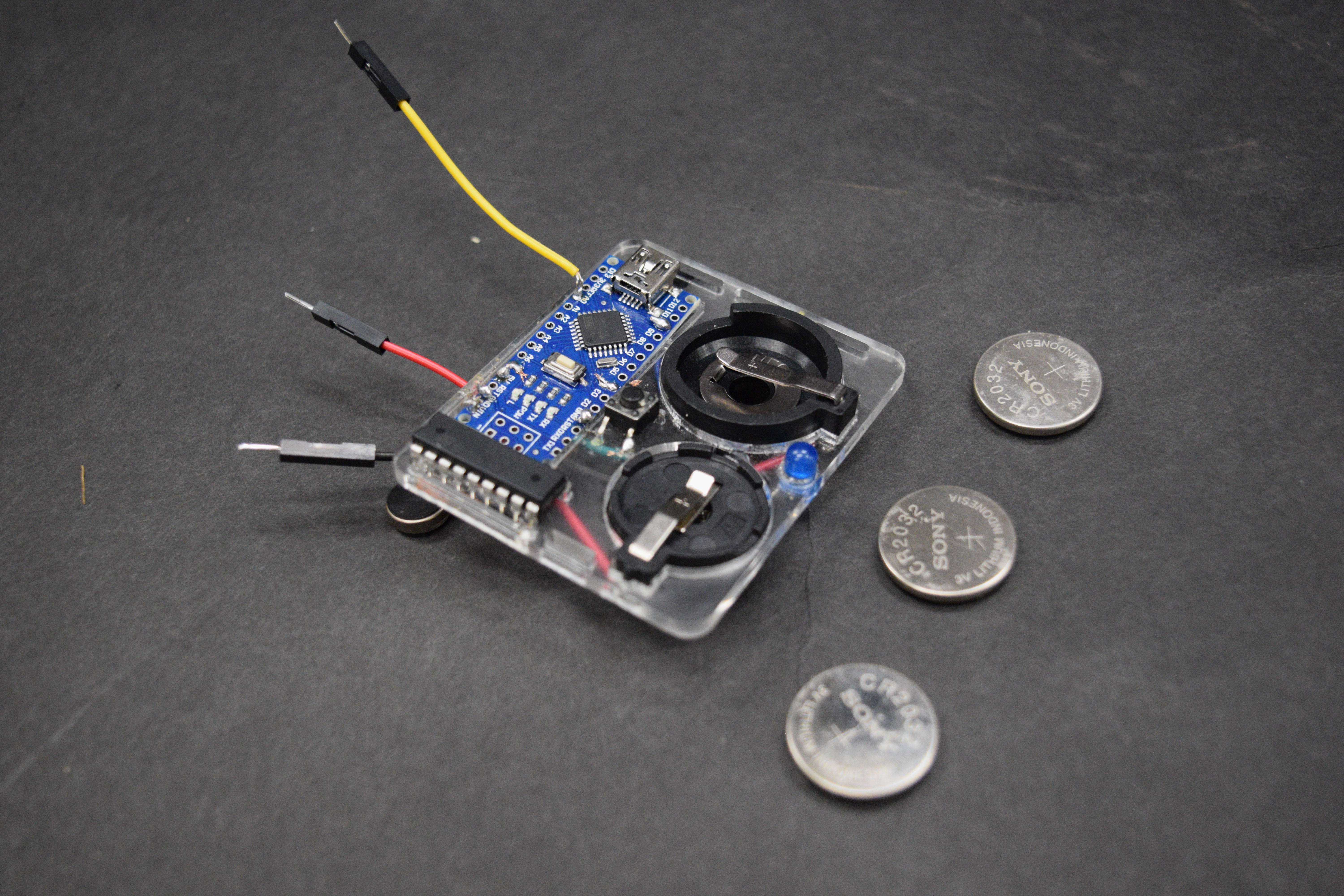
The Arduino and batteries are inserted in a slim piece of acrylic. This cuts down on weight and creates a slim comfortable wearable unit.
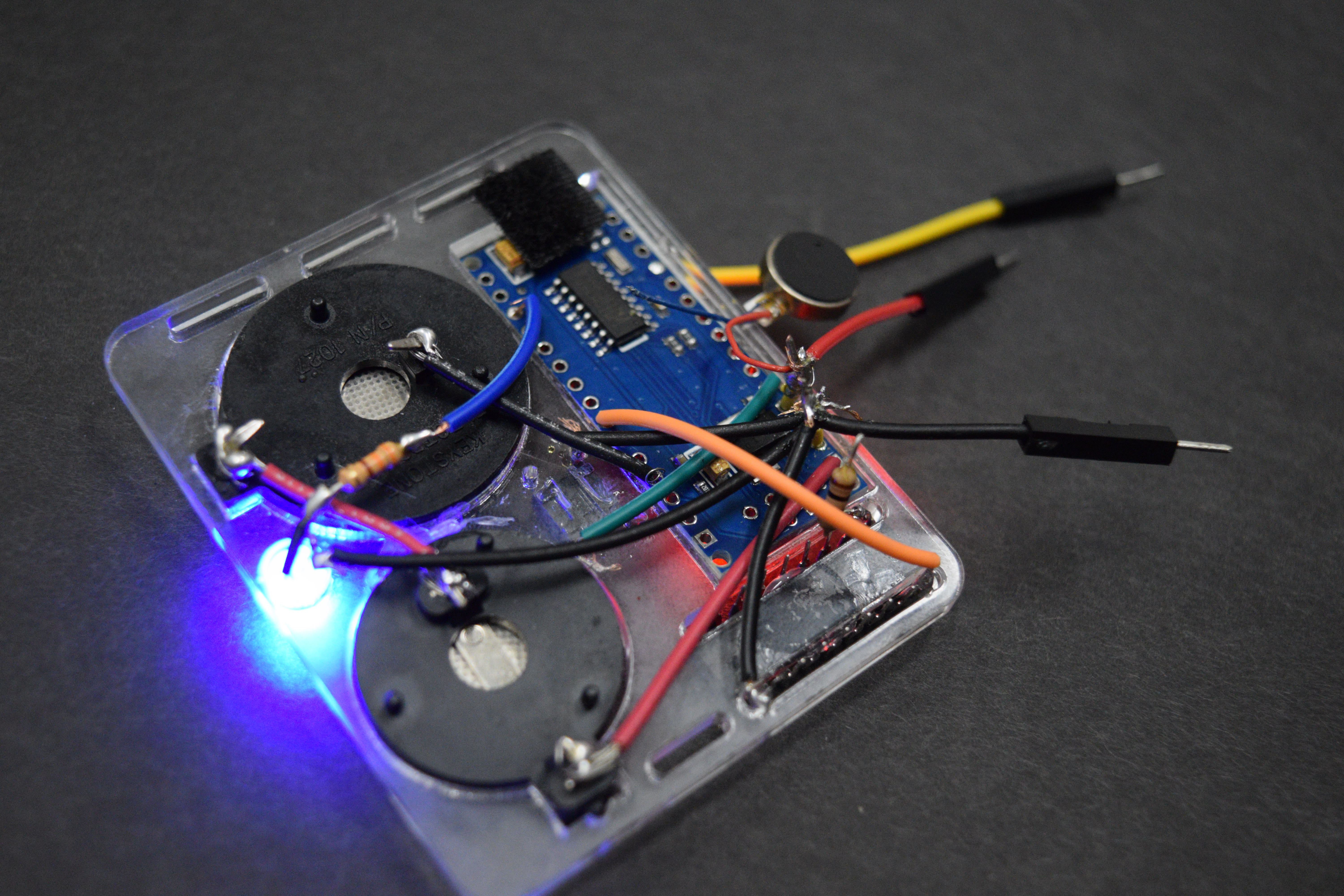
The device was wired through the back and the wires had to lay extremely flat in order to keep the device wearable.
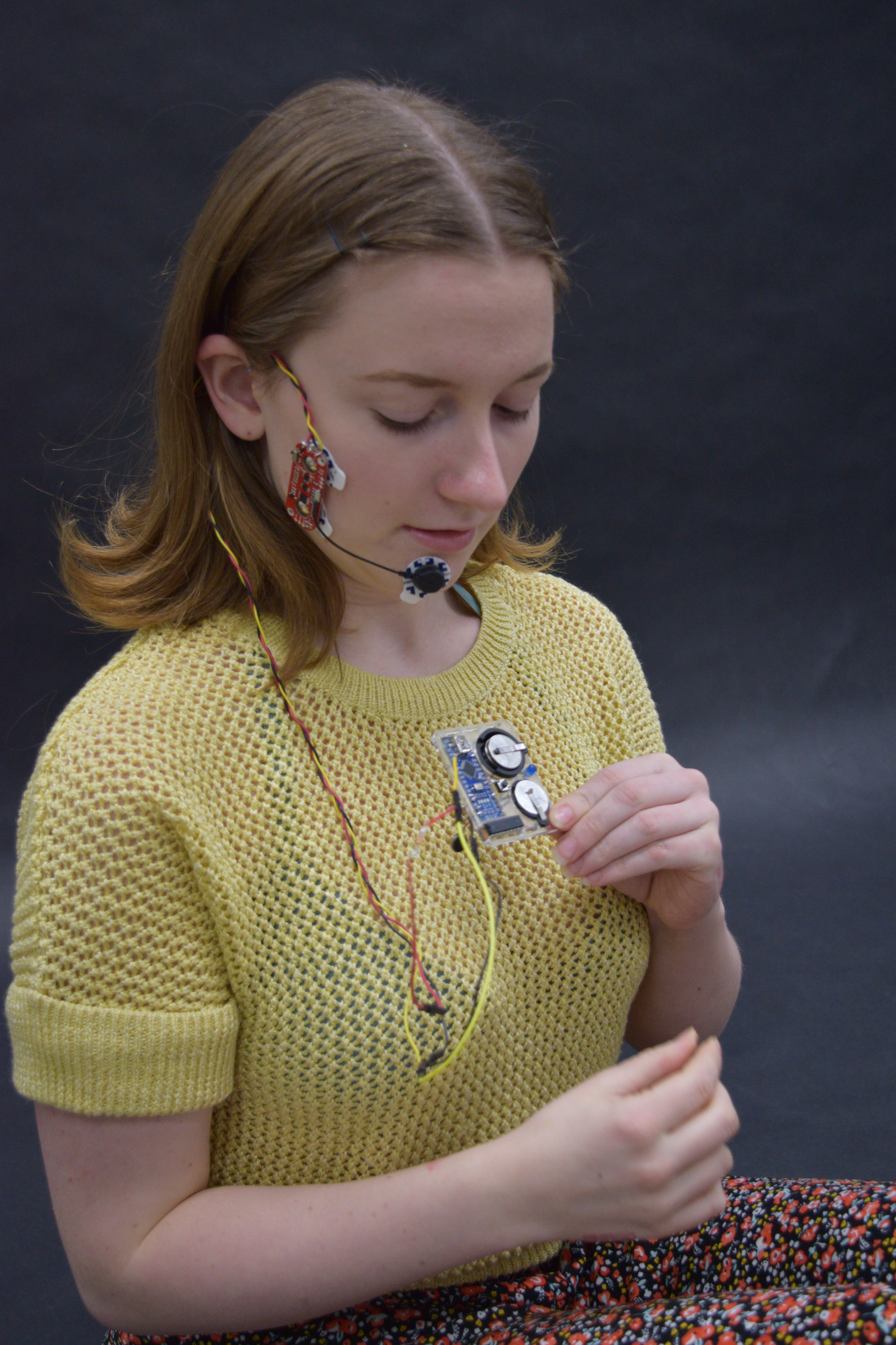
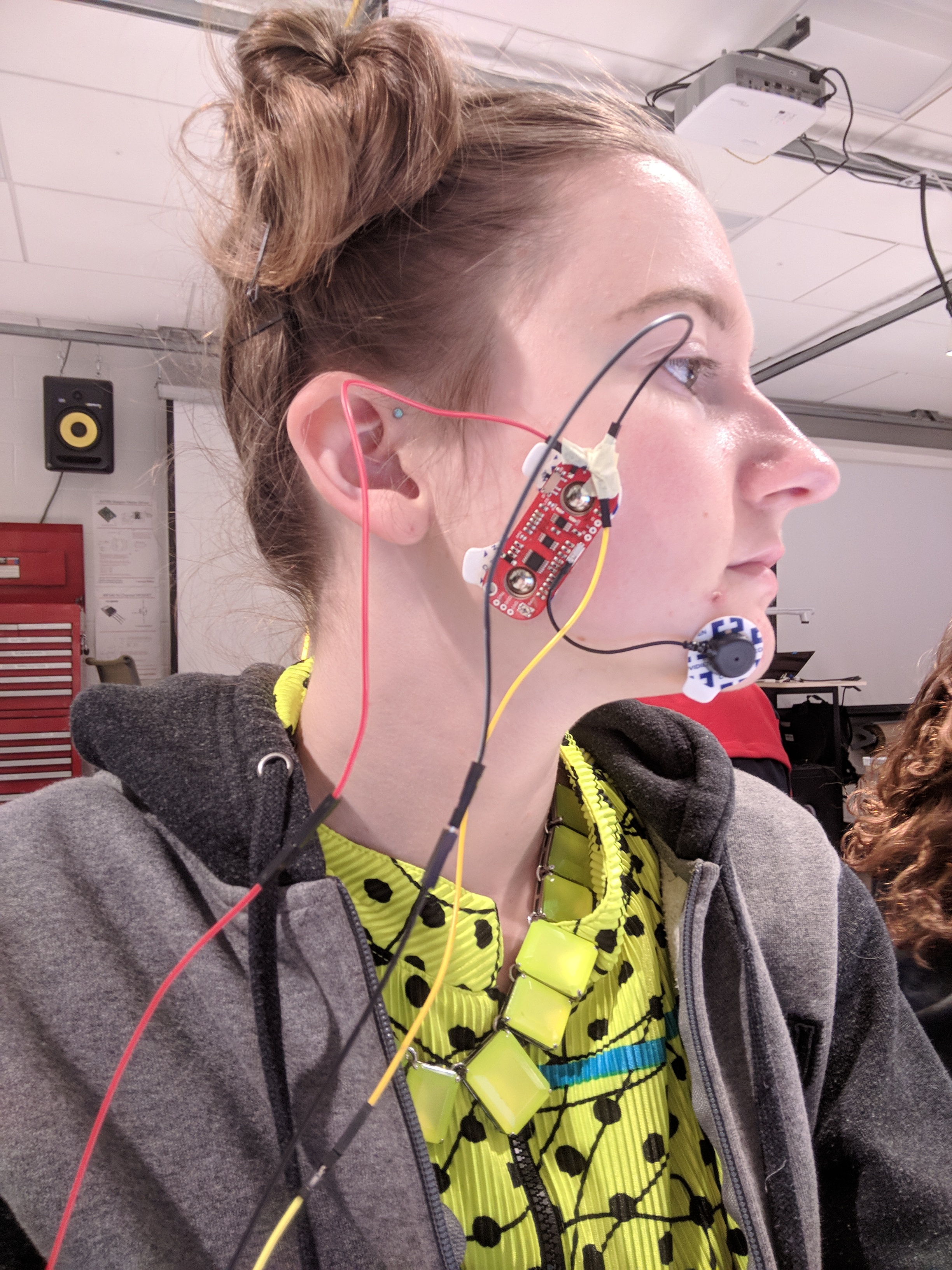
The Muscle sensor attaches to the face with medical grade electrodes and wraps over the ear. Then it runs down to where the device can rest sewn inside of a garment or hanging from a necklace. The red part of the sensor measures the middle and end of the active muscle while the black electrode measures a muscle not used when clenching your jaw. When the tension in your jaw rises above the amount set by pushing the button the blue LED lights up and activates a tiny vibrator to warn you to unclench your jaw.
Decision Point 1:
The power source: I knew I needed an external power source because I can’t carry my computer with me all day but batteries can add a lot of weight. Even AAA batteries added to much thickness to the device. I decided to go with coin batteries for their light weight and convenient size. This led to me needing a board that is less conventional than a normal bread board which would add the width of the bread board to the body of the electronic so I designed a laser cut board that the coin cell battery’s case could rest inside of.
Decision Point 2:
The button: Originally I had wanted a button to turn off the device for a “resting period” for eating and talking and a separate button for setting the current stress level and another button to turn off the vibration and light warning. This seemed to complicated for me and I played around with what facial muscles I had to work with and moved the muscle sensor and found a muscle that was not activated by speaking and chewing which allowed me to eliminate one button. Then I figured a way to write the code so that if i manually clenched my jaw to set a high stress level and hit the button then anything I did would be below that and not set off the sensor.
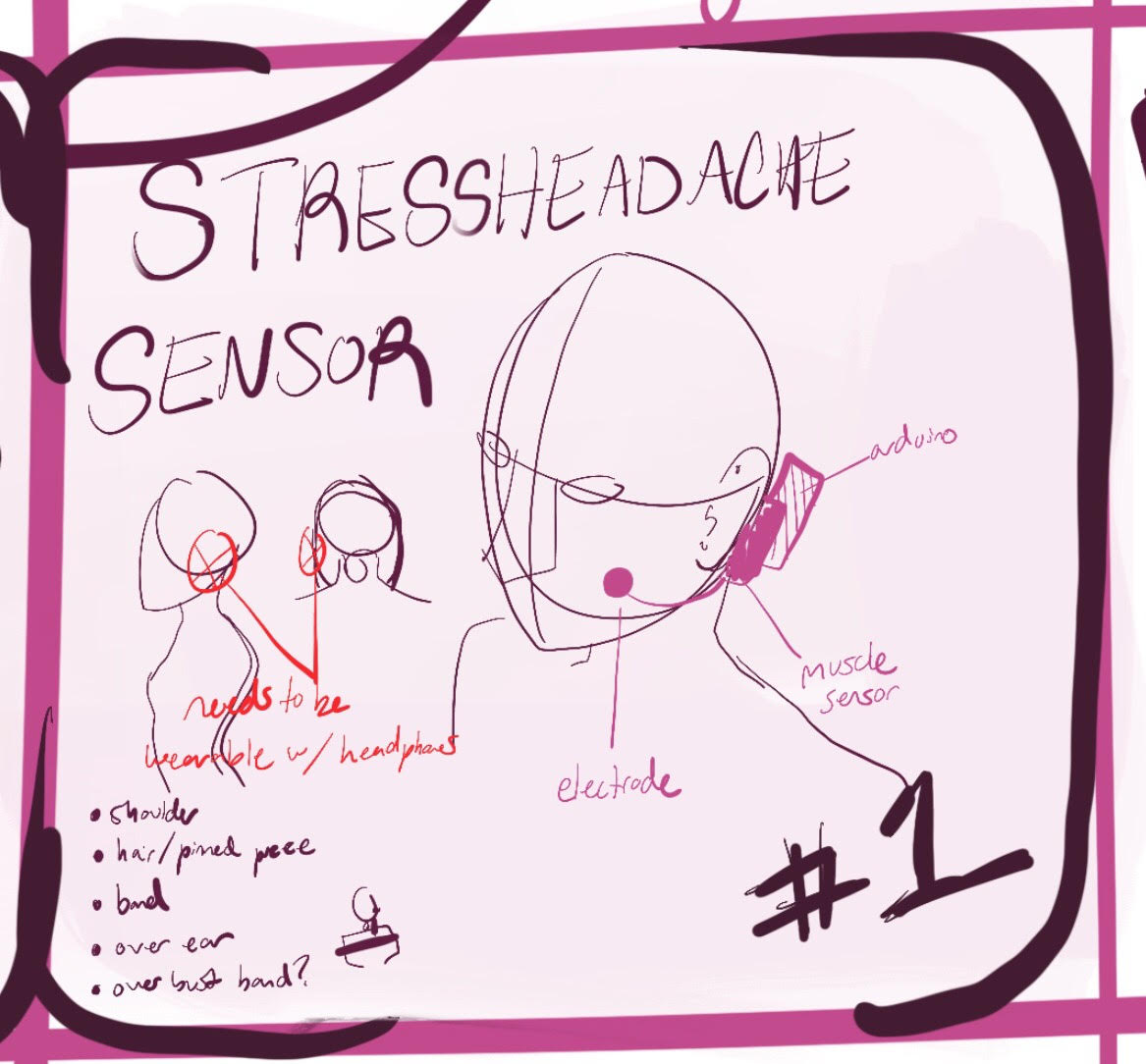
The original sketch: I ended up running the wire over the ear instead of under the ear
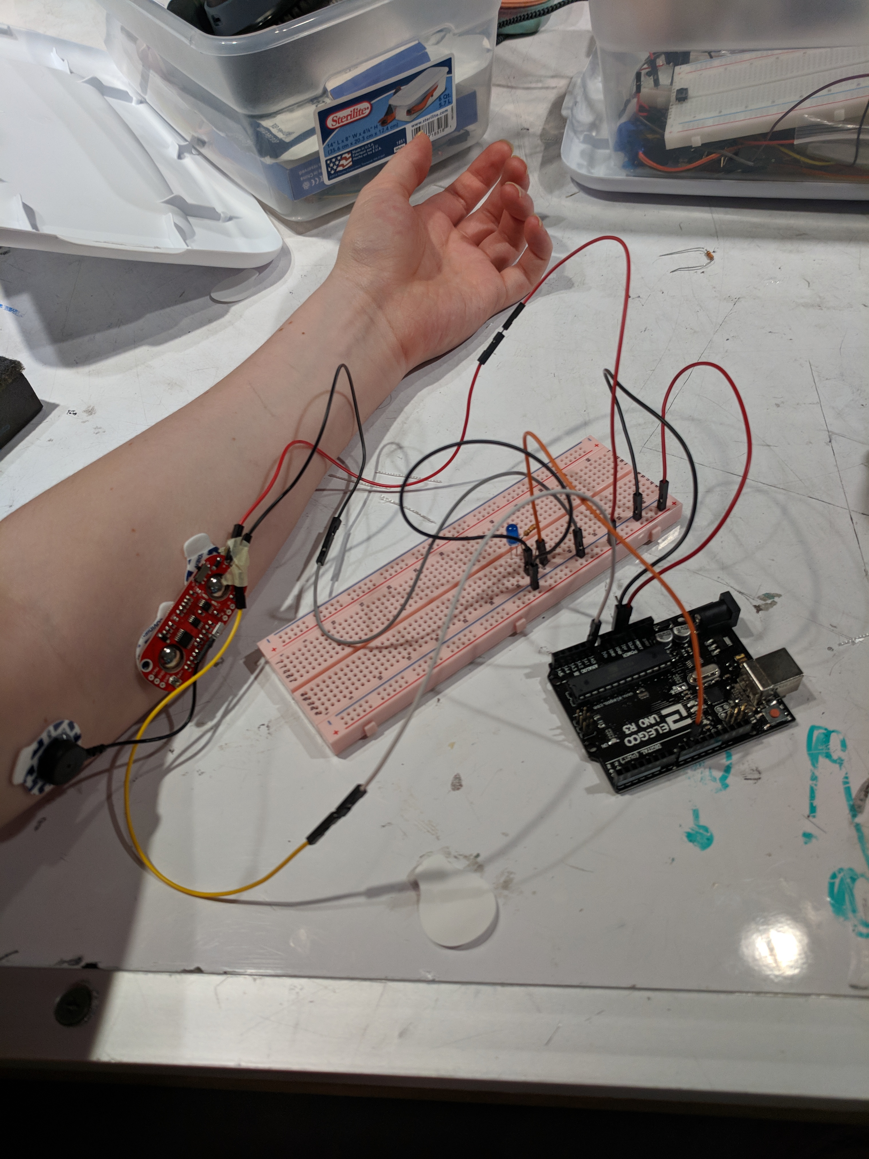
The first prototype: The vendor only has forehead and arm muscle examples so I wasn’t sure my jaw muscle was going to work. This was me making sure the technology itself worked.
First (working) Wearable Prototype: This is the final resting position of the sensor after finding a muscle that wasn’t effected by speaking or eating.
Response: I didn’t really receive much helpful feedback, most of the things were parroting what I said, which was I think I need to add more power to get it to work independently from the computer. The comments said things like: it will be good once it works without the computer. Not helpful, there weren’t any comments really digging into where this could head or something I hadn’t considered. The only comment even relevantly helpful was a suggestion that I should consider a earring form for the piece that measures the stress. I got lots of complements which in my opinion is not the purpose of a critique.
Self Critique: I am glad I got it to work, it has a long way to go but I am happy with what I consider a prototype with potential. The next steps are getting it more power, streamlining the muscle sensor, and incorporating a backing to contain the whole device. I especially like the “techy” look I finished with. All of my parts are black plastic with grey metal and blue accents, the LED and the Arduino nano. So aesthetically It’s headed in the right direction. Hopefully sometime in the future there will be a mini myoWare muscle sensor or something of a less obtrusive sensor. Hopefully adding more power will solve the unreliability of the Arduino Nano but I do see this being a product built with custom parts that could be mass produced and do quite well.
What I Learned: There will always be another prototype to follow, don’t get so hell bent on having a finished product, cut the aesthetic corners to focus on the guts, work from the inside out, not the outside in. Also pay very close attention to what your soldering together, A7 and D7 are NOT the same but easy to miss when looking for a coding error and then you get hung up on looking for an electronic problem that doesn’t exist.
Next Steps: Get the correct amount of power to get a better functioning rate then wear it for a weak straight to answer long-term questions like comfort, style, skin irritation etc. Find usable substantiates for the prototype parts and make a presentation for some friends in Tepper and see where it goes. When I explain this prototype to people many express that they would love to have one. Currently building one costs $40-50 not counting labor. But if I could get it commercially produced and sold them for around $20 a piece advertised as needing to be replaced every 6 months I’d make a killing.
Long-Term=money
Short-Term=prototype for personal use.
- /*
- Stress Less
- Claire Mildred
- When a button is pushed the current stress level is saved into a variable, when the code reads the current stress is higher than the stress saved in the variable it sets out a light and activates the vibrator.
- Code that came with the MyoWare part:
- Analog input, analog output, serial output
- Reads an analog input pin, maps the result to a range from 0 to 255 and uses
- the result to set the pulse width modulation (PWM) of an output pin.
- Also prints the results to the Serial Monitor.
- The circuit:
- - potentiometer connected to analog pin 0.
- Center pin of the potentiometer goes to the analog pin.
- side pins of the potentiometer go to +5V and ground
- - LED connected from digital pin 9 to ground
- created 29 Dec. 2008
- modified 9 Apr 2012
- by Tom Igoe
- This example code is in the public domain.
- http://www.arduino.cc/en/Tutorial/AnalogInOutSerial
- */
- // These constants won't change. They're used to give names to the pins used:
- const int analogInPin = A0; // Analog input pin that the potentiometer is attached to
- const int analogOutPin = 9; // Analog output pin that the LED is attached to
- const int VIBE = 4; //digital output that gives power to the vibe
- const int button= 7;
- const int light=10;
- int stress;
- int sensorValue = 0; // value read from the pot
- int outputValue = 0; // value output to the PWM (analog out)
- int ButtonRead;
- void setup() {
- // initialize serial communications at 9600 bps:
- Serial.begin(9600);
- // setup vibrator on/off
- pinMode(VIBE, OUTPUT);
- pinMode(button,INPUT_PULLUP);
- pinMode(light,OUTPUT);
- }
- void loop() {
- //MYOWARE MUSCLE SENSOR CODE
- // read the analog in value:
- sensorValue = analogRead(analogInPin);
- // map it to the range of the analog out:
- outputValue = map(sensorValue, 0, 1023, 0, 255);
- // change the analog out value:
- analogWrite(analogOutPin, outputValue);
- //WHEN BUTTON IS PUSHED CURRENT SRESS IS READ
- ButtonRead=digitalRead(button);
- if (ButtonRead == 0){
- stress=sensorValue+20;
- }
- //VIBRATOR OUTPUT CODE
- digitalWrite(VIBE,LOW);
- digitalWrite(light,LOW);
- if (stress <= sensorValue){
- digitalWrite(VIBE,HIGH);
- digitalWrite(light,HIGH);
- }
- //RETURN SERIAL NUMBERS FOR OBSERVATION
- // print the results to the Serial Monitor:
- Serial.print("button is ");
- Serial.print(ButtonRead);
- Serial.print(", sensor = ");
- Serial.print(sensorValue);
- Serial.print("\t output = ");
- Serial.println(outputValue);
- //END OF PARTS, DELAY FOR ACCURACY
- // wait 2 milliseconds before the next loop for the analog-to-digital
- // converter to settle after the last reading:
- delay(10);
- }
Leave a Reply
You must be logged in to post a comment.